
System for and method of image processing and computer program for causing computer to execute the method

a technology of image processing and computer program, which is applied in the field of image processing system and computer program for causing computer to execute the method, can solve the problems of reddish color of the image, inability to be faithful to the object, and the noise included in the image obtained by photographing becoming more serious as the sensitivity increases, so as to reduce the noise, accurately detect the noise, and reduce the effect of nois

Inactive Publication Date: 2011-07-19
FUJIFILM CORP
View PDF9 Cites 5 Cited by
  • Summary
  • Abstract
  • Description
  • Claims
  • Application Information

AI Technical Summary

Benefits of technology

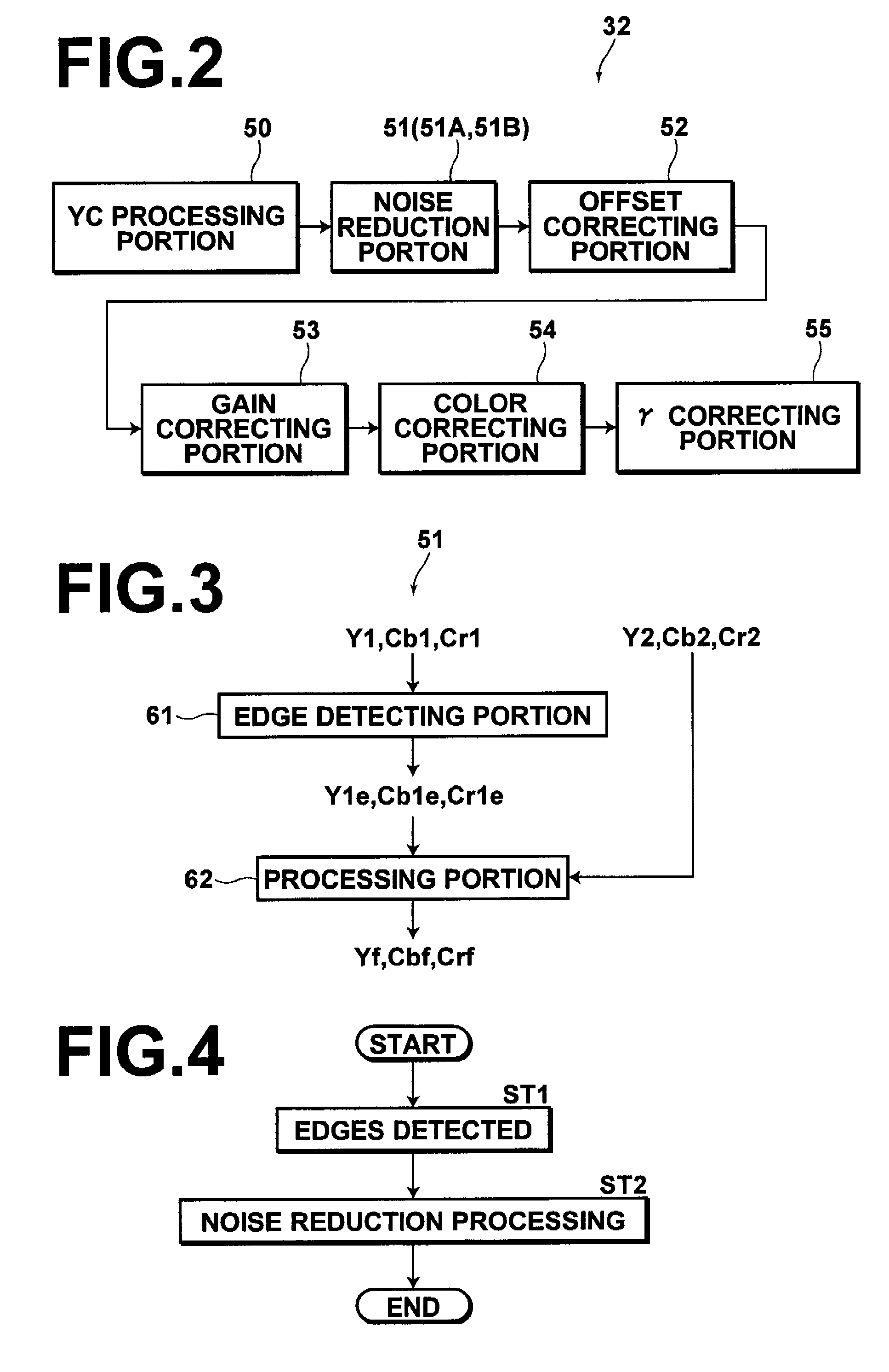
The present invention provides an image processing apparatus and method for accurately detecting edges in an image and reducing noise in the image without affecting the edges. The apparatus and method use an edge detecting means to identify edges in the image, a difference detecting means to identify differences between the images, and a noise reduction means to process the image to avoid the edges. The apparatus and method can be used in image processing apparatuses and methods that obtain images by photographing without or with an infrared ray cut filter. The technical effects of the invention include improved image quality and reduced noise in the image.

Problems solved by technology

Since the CCD is sensitive to light in the infrared region, the reproduced color becomes reddish and cannot be faithful to the object when all the light from the object is imaged on the CCD.
Though the CCD has been increased in the number of pixels and the sensitivity, the problem of the noises included in an image obtained by photographing becomes more serious as the sensitivity becomes higher.
However, in the image obtained by the high-sensitive photographing, there are included very lots of noises and at the same time, the noise signal is sometimes larger in the amplitude than the edge signal included in the image, whereby it becomes difficult to distinguish the noise and the edge from each other.
When the noise and the edge cannot be distinguished from each other, it is impossible to avoid the edges when the noises are reduced.

Method used


Image

  • System for and method of image processing and computer program for causing computer to execute the method
  • System for and method of image processing and computer program for causing computer to execute the method
  • System for and method of image processing and computer program for causing computer to execute the method

Examples


first embodiment

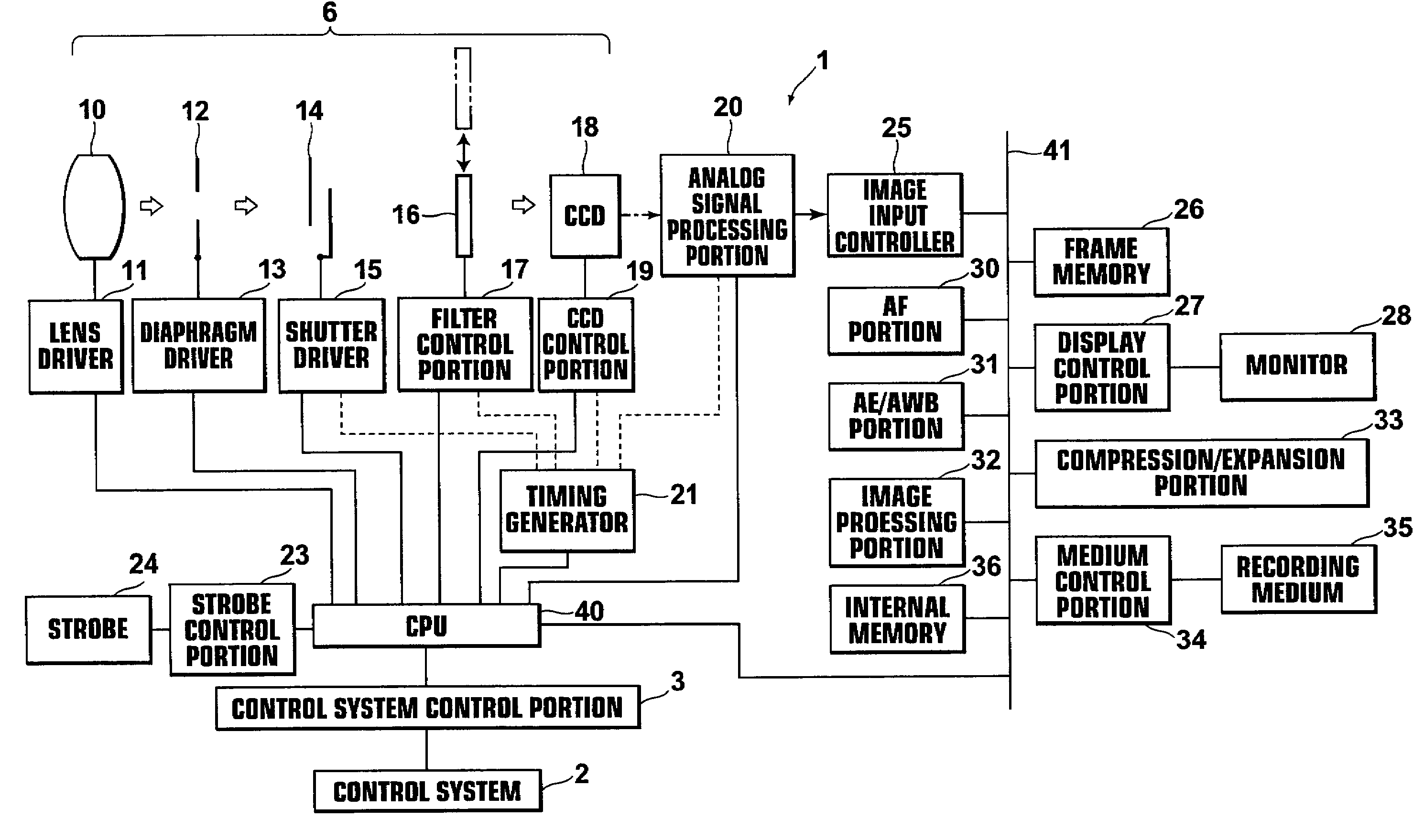
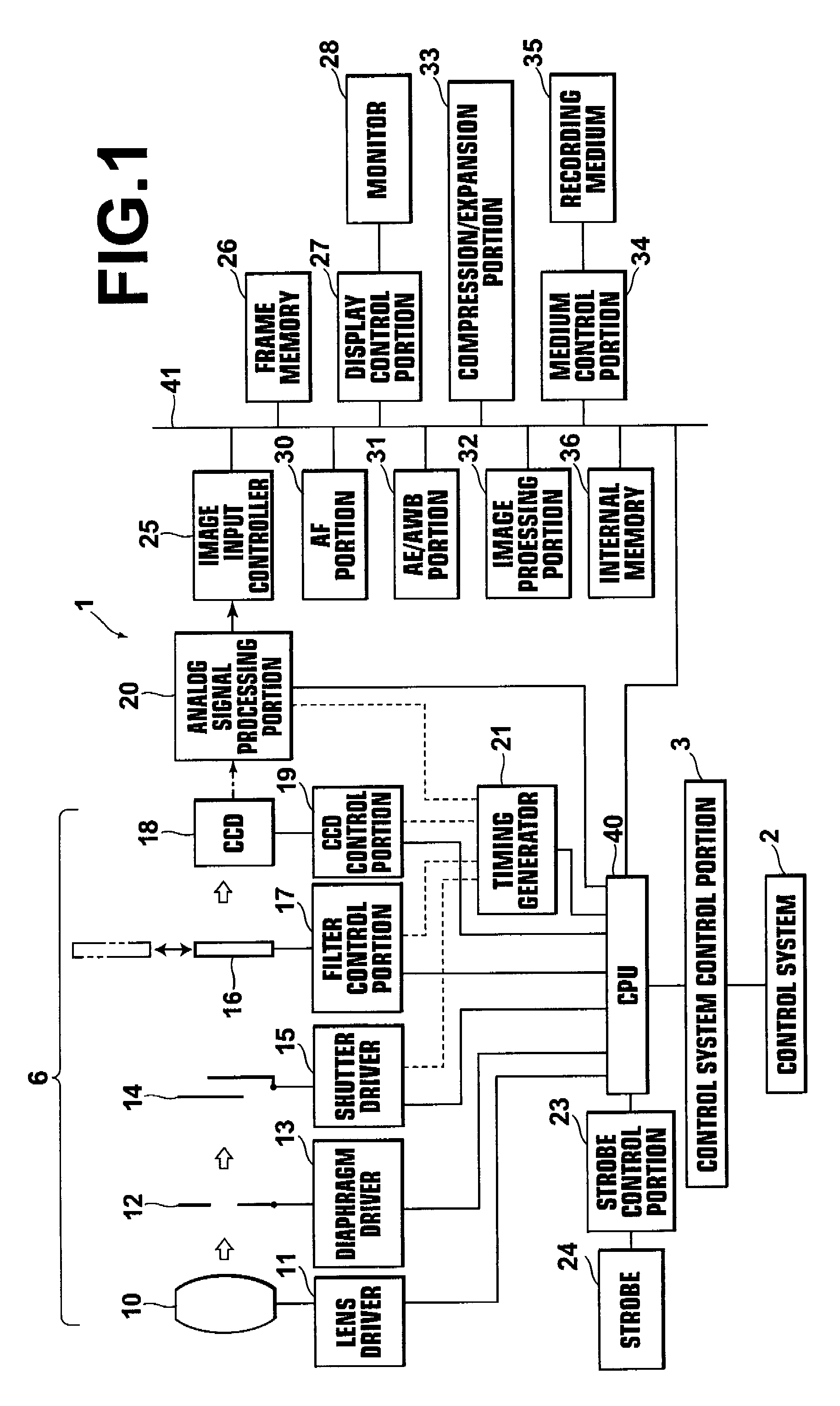
[0066]The embodiments of the present invention will be described with reference to the drawings, hereinbelow. FIG. 1 is a block diagram showing a digital camera to which an image processing system in accordance with the present invention is applied. As shown in FIG. 1, the digital camera 1 of this embodiment has a control system 2 comprising an action mode switch, a zoom lever, an up and down / right and left button, shutter release button, power switch and the like and a control system control portion 3 which is an interface for transmitting the contents of control by the control system 2 to the CPU 40.

[0067]As the image taking system 6, the digital camera 1 of this embodiment has a taking lens 10 comprising a focusing lens and a zoom lens. The focusing lens and the zoom lens making up the taking lens 10 are movable in the direction of the optical direction by a lens drive portion 11 comprising a motor and a motor driver.

[0068]A diaphragm 12 is driven by a diaphragm driver 13 compris...

second embodiment

[0112]In the second embodiment, when the absolute value |B1(i,j)−B2(i,j)| of the difference of the pixel values as calculated by the difference detecting portion 72 is not larger than the threshold value Th1, the noise reduction processing is carried out to avoid the edges on the basis of the edge images Y1e, Cb1e and Cr1e which are accurately detected without affected by the noises and when the absolute value |B1(i,j)−B2(i,j)| of the difference of the pixel values is larger than the threshold value Th1, the noise reduction processing is carried out to avoid the edges on the basis of the edge images Y2e, Cb2e and Cr2e which is superior to the edge images Y1e, Cb1e and Cr1e in accurately representing the position of edges in the second image S2 though affected by the noises in this manner. Accordingly, while the edges are accurately detected by the use of the first image S1, the noise reduction processing can be carried out to avoid the edges contained in the second image S2 even if ...

third embodiment

[0121]In the third embodiment, the position of edges in the edge images Y1e, Cb1e and Cr1e is corrected on the basis of the movement detected by the movement detecting portion 82 and the noise reduction processing is carried out on the images Y2, Cb2, and Cr2 to avoid the edges in corrected positions. Accordingly, while the edges are accurately detected by the use of the first image S1, the noise reduction processing can be carried out to avoid the edges contained in the second image S2 even if the object is moved. As a result, a processed image in which the noises are reduced can be obtained without blurring the edges.

[0122]Though, in the third embodiment described above, the images B1 and B2 represented by B1 and B2 data are used, Y1 image and Y2 image may be used instead of the images B1 and B2. Further, the Cb1 image and the Cb2 image or the Cr1 image and the Cr2 image may be used. Even the G1 image and the G2 image or the R1 image and the R2 image may be used.

[0123]Though, in t...


PUM


Abstract

An image processing apparatus includes an edge detecting portion which detects edges contained in a first image, out of first and second images representing the same object, one being obtained by photographing without the infrared ray cut filter, the other being obtained by photographing with the infrared ray cut filter, and a noise reduction portion which carries out noise reduction processing on the second image to avoid the edges and obtains a processed image.

Description

BACKGROUND OF THE INVENTION[0001]1. Field of the Invention[0002]This invention relates to a system for and a method of image processing where noises included in an image obtained by photographing are reduced, and a computer program for causing a computer to execute the method.[0003]2. Description of the Related Art[0004]There has been known a digital camera in which an infrared ray cut filter is retractably inserted into the optical path of a taking system such as a CCD to eliminate the light in an infrared region from the incident light so that the photographing can be carried out both with and without the infrared ray cut filter (See Japanese Unexamined Patent Publication No. 6 (1994)-141247). Since the CCD is sensitive to light in the infrared region, the reproduced color becomes reddish and cannot be faithful to the object when all the light from the object is imaged on the CCD. Accordingly, in such a camera, the photographing is carried out with the infrared ray cut filter in t...

Claims


Application Information

Patent Timeline
Patent Type & Authority Patents(United States)
IPC IPC(8): H04N5/217G06T5/00G06V10/143G06V10/30H04N1/409H04N5/21H04N23/76
CPCG06K9/2018G06K9/40G06T5/002G06T7/0022H04N5/217H04N5/2254H04N5/232H04N5/23232H04N9/045G06T2207/10152G06T2207/20012G06T2207/20192G06T7/97G06V10/143G06V10/30H04N23/81H04N23/673H04N23/951G06T5/70
Inventor IZAWA, KATSUTOSHI
Owner FUJIFILM CORP
Learn More