
Combined salt and pepper mill

a spice mill and milling machine technology, applied in the field of spice mills, can solve the problems of reducing affecting the production efficiency of spice mills, and comparatively awkward addition of condiments to their respective containers, and achieves the effect of simple construction and simple manner

Inactive Publication Date: 2011-07-12
PI-DESIGN AG
View PDF6 Cites 10 Cited by
  • Summary
  • Abstract
  • Description
  • Claims
  • Application Information

AI Technical Summary

Benefits of technology

The present invention provides a spice mill with two separate containers for different condiments that can be easily added. The spice mill has a simple construction and allows for easy cleaning. The grinding mechanisms are driven by a gear mechanism that is encapsulated and can be located in the upper region of the base part. The gear mechanism is designed to selectively drive either the first or second grinding mechanism, depending on the direction of rotation of the cover part. The spice mill allows for broad configurational flexibility and has a circular outline. A guide bush is formed to mount and guide the cover part, and the gear mechanism is driven by a drive shaft that can be connected to the cover part in a non-positive or positive manner. The gear mechanism is a development of a gear mechanism disclosed in U.S. Pat. No. 4,709,865.

Problems solved by technology

This spice mill has the drawback that it is comparatively awkward to add the condiments to their respective containers.
In addition, the proposed design does not allow the spice mill to be produced with a round outline, as it would not be possible in this case to rotate the covering in such a way as to allow the spices to be added.
The possible configurations are therefore limited.
Furthermore, the construction of this spice mill is comparatively complex, as a tensile spring force has to be provided in order to prestress the covering downward when closed.
The gear mechanism of this spice mill can become contaminated when the condiments are added and as a result become damaged.
One drawback of this design is that the cover part becomes very large and heavy.

Method used


Image

  • Combined salt and pepper mill
  • Combined salt and pepper mill
  • Combined salt and pepper mill

Examples


Embodiment Construction

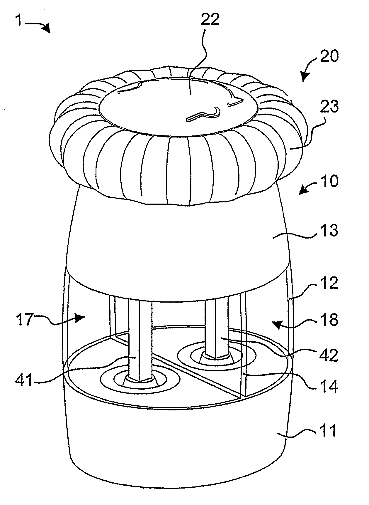
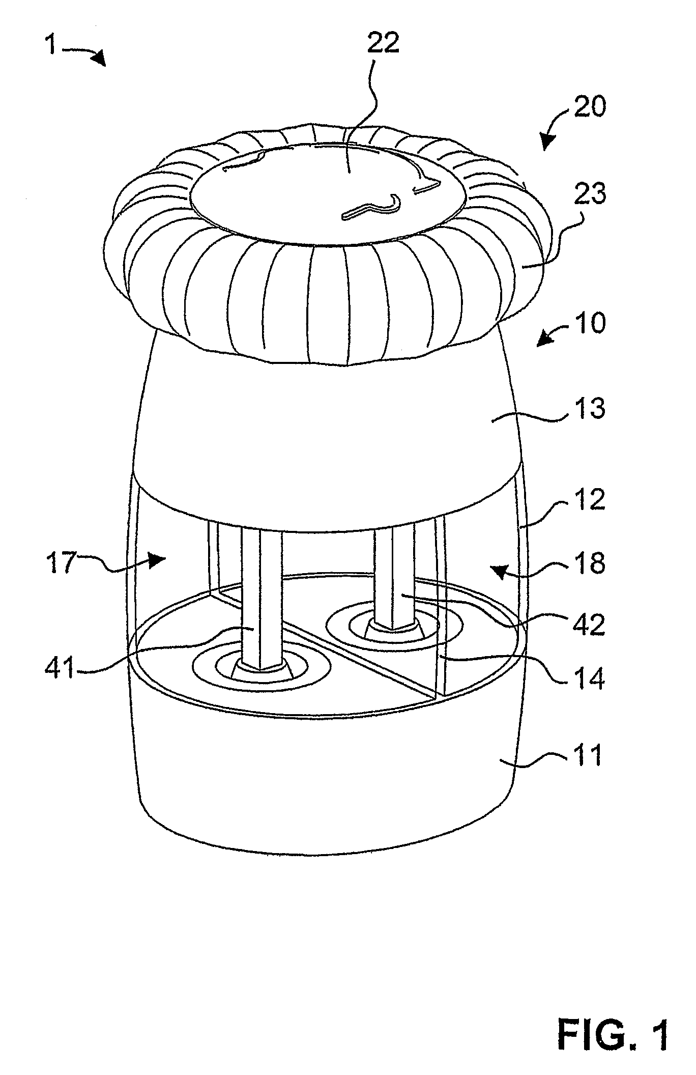
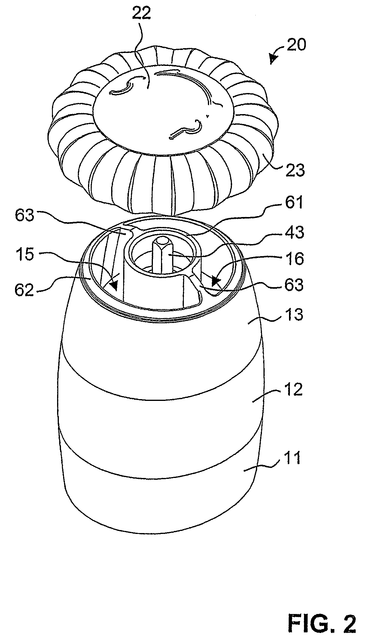
[0025]FIGS. 1 to 4 are various views of a salt and pepper mill according to the invention.

[0026]The salt and pepper mill 1 has a base part 10 and a cover part 20 which can be removed therefrom. The base part 10 has a multipart housing comprising in particular a housing lower part 11, a transparent wall 12 and a housing upper part 13. The housing is divided by a partition 14 into two separate spice containers, namely a salt container 17 and a pepper container 18.

[0027]Obviously, the mill is however also suitable for other condiments. The housing lower part 11 forms the bottom of these containers, a respective grinding mechanism 50 or 50′ being arranged in each container bottom. The grinding mechanisms are conventionally constructed, with a conical grinding wheel 52, 52′ as the rotor running in a counter bearing 51, 51′, also referred to as the grinding cylinder, as the stator. Each of the grinding wheels 52, 52′ is fixed to a respective square shaft 41, 42 by a fixing nut 53, 53′ for...


PUM


Abstract

A spice mill for cutting up two different spices, in particular salt and pepper, is disclosed. Two spice containers (17, 18) and two grinding mechanisms (50, 50′) are arranged in a base part (10). A cover part (20) can be removed from the base part (10) and serves as a rotary handle. When the cover part (20) is removed, filling openings (15, 16) for the spice containers (17, 18) are opened up. An encapsulated gear mechanism (30) is arranged in the base part (10) between the cover part and the grinding mechanisms. When the cover part (20) is rotated in a first direction of rotation, the gear mechanism (30) drives the first grinding mechanism (50). By contrast, upon rotation in the opposite direction, the second grinding mechanism (50′) is driven. In a preferred embodiment, the gear mechanism is arranged in an upper region of the base part and, together with the base part, bounds the filling openings.

Description

TECHNICAL FIELD[0001]The present invention relates to a spice mill for crushing two different condiments, in particular salt and pepper.PRIOR ART[0002]U.S. Pat. No. 4,709,865 discloses a spice mill having two separate spice containers which can receive different condiments, for example peppercorns and salt crystals. A grinding mechanism is provided at the bottom of each spice container to crush the condiments. Starting from the grinding mechanisms, a shaft extends upward through each of the spice containers to drive the grinding mechanism in question, a gear wheel being attached to the upper end of each shaft. Provided at the upper end of the spice containers is a gear mechanism containing a pivotable gear wheel which enters into engagement with the gear wheel on one shaft when the gear mechanism is driven in one direction and enters into engagement with the gear wheel of the other shaft when the gear mechanism is driven in the opposite direction. The containers are upwardly sealed ...

Claims


Application Information

Patent Timeline
Patent Type & Authority Patents(United States)
IPC IPC(8): A47J17/18A47J17/00A47J43/00
CPCA47J42/04A47J42/46
Inventor BODUM, JORGEN
Owner PI-DESIGN AG
Learn More