
Continuous positive airway pressure device by controlling the pressure in the face mask

a technology of positive airway pressure and face mask, which is applied in the direction of valves, mechanical devices, operating means/releasing devices, etc., can solve the problems of affecting the breathing of patients, affecting the breathing of people, etc., to achieve the effect of precisely detecting and controlling the breath of patients

Inactive Publication Date: 2011-07-12
CHA EUN JONG +3
View PDF4 Cites 6 Cited by
  • Summary
  • Abstract
  • Description
  • Claims
  • Application Information

AI Technical Summary

Benefits of technology

This solution enables precise pressure control and breath detection with reduced manufacturing costs by simplifying the control circuit and eliminating the need for multiple sensors, ensuring accurate positive pressure delivery and efficient operation.

Problems solved by technology

However, some persons snore when breathing in due to the narrowed trachea or experience sleep apnea.
When the sleep apnea continues, the arterial oxygen saturation is excessively reduced, so circulatory disease such as hipertension, arrhythmia, ischemic heard disease, heart failure or cerebral palsy may easily occur.
Further, the sleep apnea may cause insulin insufficiency, which is the main factor of diabetes, or may cause pulmonary disease / heart disease to become worse.
In addition, the sleep apnea may cause sudden death during sleeping.
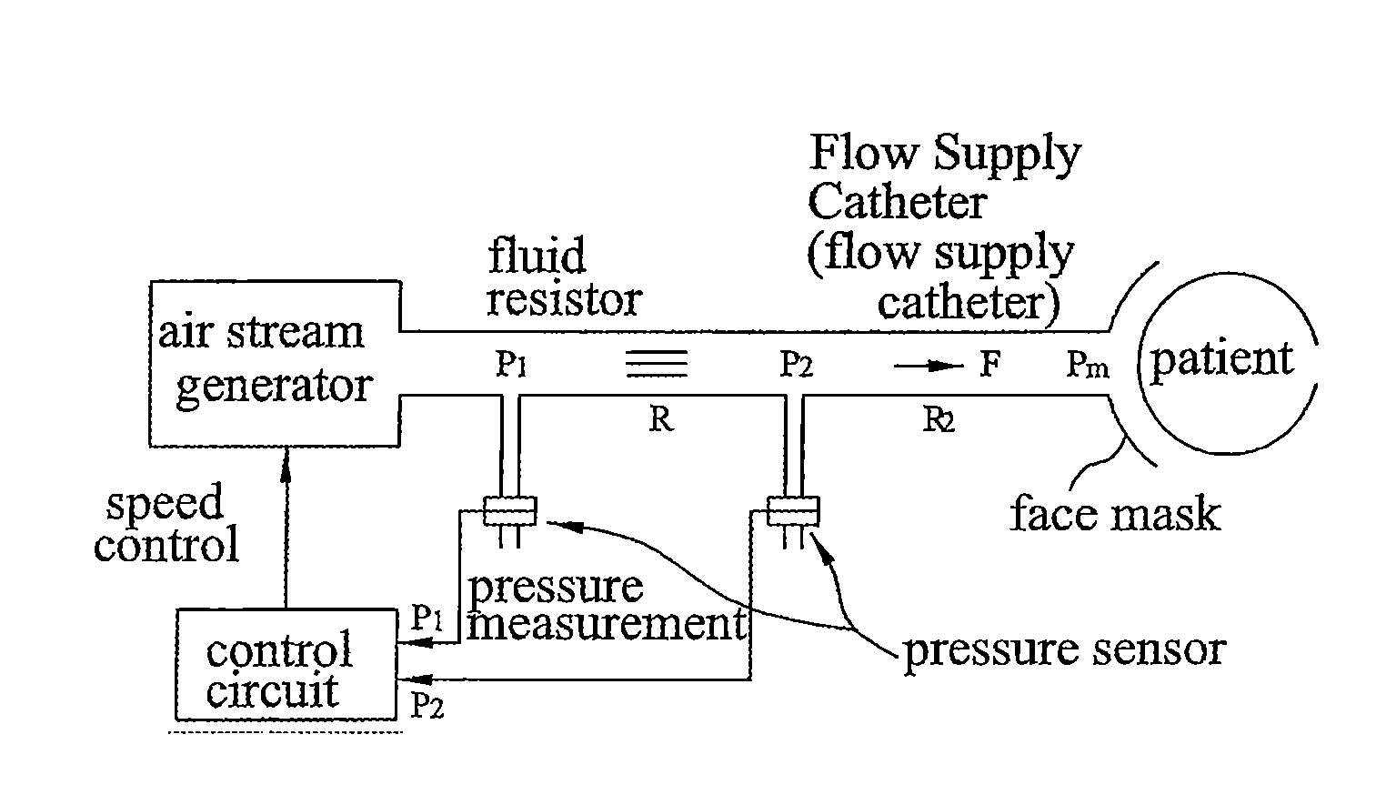
This is because it is inconvenient to install the pressure sensors, and the flow supply catheter and electric wire, which interconnect with the pressure sensors, around the face mask worn by a patient.
First, two pressure values must be measured to generate air stream such that Pm has a constant value (positive pressure) through Equation 3. Since P1 and P2 are essentially changed according to the generated air stream, the number (i.e. two) of control parameters is increased, causing the waste of circuit sources.
Second, providing that Rc has a value of 0 in Equation 3, P2 becomes equal to Pm and only P2 is controlled. However, since the fluid resistance of the flow supply catheter is always larger than 0, the control cannot be exactly performed.
Third, since the CPAP device is a medical instrument for preventing a patient from dying due to the sleep apnea during sleeping, it must be monitored whether the patient is spontaneously breathing. This can be achieved by detecting oscillation of pressure Pm in the face mask, which is caused by spontaneous breathing of the patient, on the basis of a target control value. In such a case, since P2 cooperates with Pm, a method of determining if the patient is spontaneously breathing by detecting the oscillation of P2 is used. However, since the flow supply catheter has a long length (>70 cm) and Rc≠0, P2 is less oscillated as compared with Pm. Thus, an error may occur in the breath detecting function.
Last, since two pressure sensors and one fluid resistor are used, the manufacturing cost is expensive.

Method used


Image

  • Continuous positive airway pressure device by controlling the pressure in the face mask
  • Continuous positive airway pressure device by controlling the pressure in the face mask
  • Continuous positive airway pressure device by controlling the pressure in the face mask

Examples


Embodiment Construction

[0036]Hereinafter, a preferred embodiment of the present invention will be explained in detail with reference to the accompanying drawings.

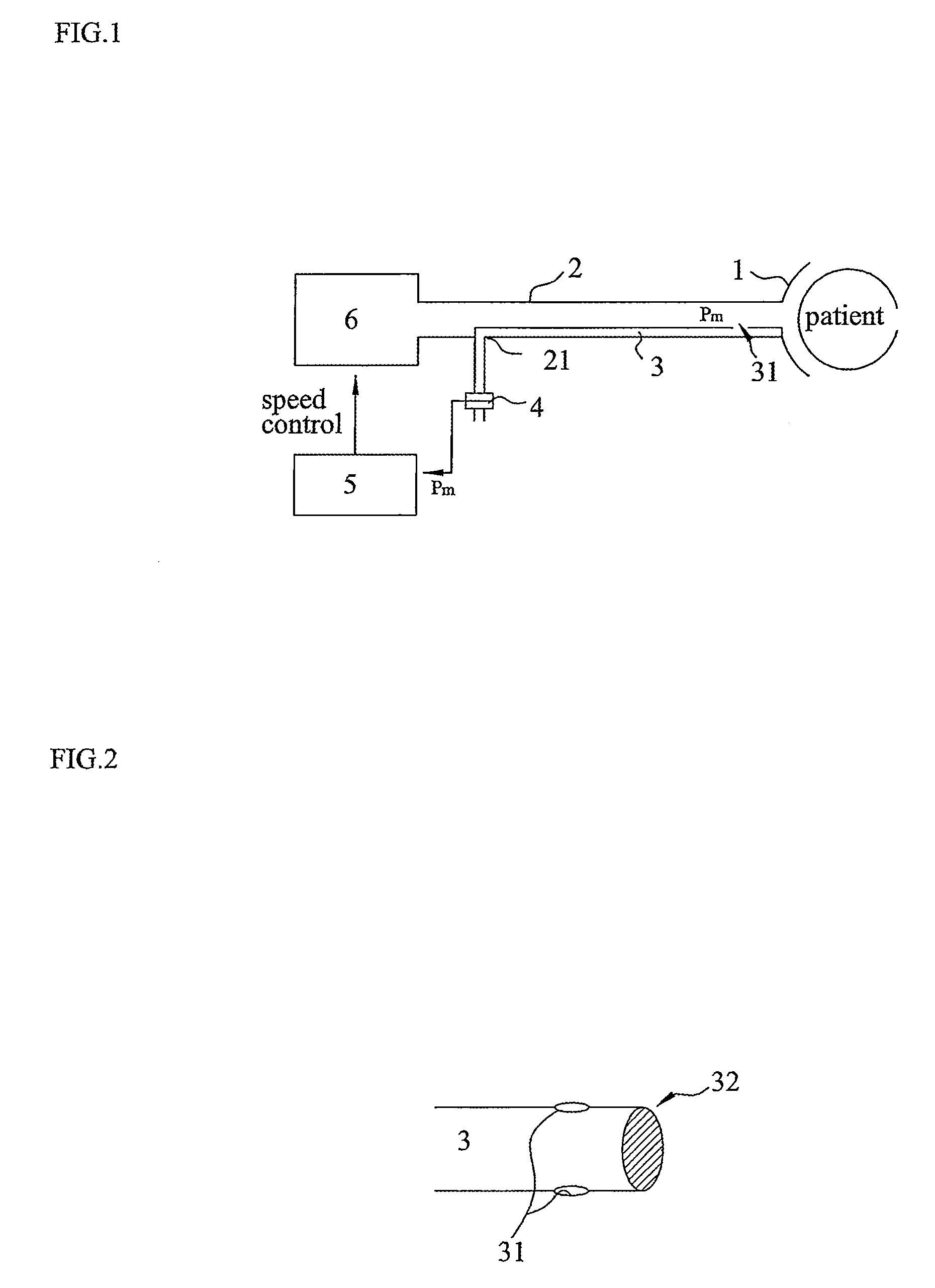
[0037]FIG. 1 is a block diagram schematically showing the construction of a CPAP device according to the present invention. As shown in FIG. 1, the CPAP device comprises a pressure detection pipe 3, a pressure sensor 4, a control circuit 5 and an air stream generator 6. The pressure detection pipe 3 has one side, which is installed such that a detection hole 31 is located at a connection portion between a face mask 1 and a flow supply catheter 2 in order to directly measure pressure Pm in the face mask 1. Further, the pressure detection pipe 3 has the other side connected to the pressure sensor 4 through a through hole 21 formed in the flow supply catheter 2. The pressure sensor 4 is connected to the other side of the pressure detection pipe 3 to measure the pressure of the detection hole 31 formed at the first side of the pressure detection pipe...


PUM


Abstract

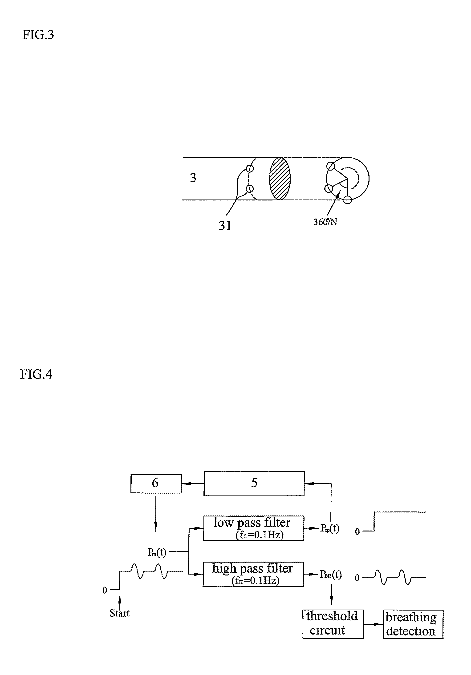
A CPAP device includes an air stream generator for generating positive pressure, a face mask connected to the air stream generator through a flow supply catheter, a pressure sensor measuring pressure in the face mask, a control circuit controlling the air stream generator, and a pressure detection pipe having a first side and a second side. The pressure sensor is connected to the second side of the pressure detection pipe to measure pressure of the detection hole formed at the first side of the pressure detection pipe and outputs the measured pressure value to the control circuit. The control circuit distinguishes average positive pressure from pressure caused by spontaneous breathing of patient according to values of the pressure in the face mask, which are input from the pressure sensor, and controls a speed of the air stream generator such that preset positive pressure is supplied to the patient.

Description

BACKGROUND OF THE INVENTION[0001]1. Field of the Invention[0002]The present invention relates to a CPAP (continuous positive airway pressure) device controlling pressure in a face mask. More particularly, the present invention relates to a device for supplying proper positive pressure by using a structure precisely measuring the breathing state of a patient.[0003]2. Description of the Related Art[0004]In general, when a person sleeps, all the muscles in the body of the person are relaxed. In addition to muscles of the trachea, muscles of the uvula or the throat are also relaxed, so the diameter of the trachea is reduced. Even if the diameter of the trachea is slightly reduced during sleeping, most persons feel no difficulty in breathing. However, some persons snore when breathing in due to the narrowed trachea or experience sleep apnea.[0005]When the sleep apnea continues, the arterial oxygen saturation is excessively reduced, so circulatory disease such as hipertension, arrhythmia,...

Claims


Application Information

Patent Timeline
Patent Type & Authority Patents(United States)
IPC IPC(8): A61M11/00
CPCA61M16/0051A61M16/0066A61M16/0069A61M2016/0027A61M2205/3365A61M16/024
Inventor CHA, EUN JONGKIM, KYUNG AHKIM, SEONG SIKKANG, SEUNG BUM
Owner CHA EUN JONG
Learn More