
Electronic article surveillance deactivator using visual pattern recognition system for triggering

a technology of electronic article surveillance and visual pattern recognition, applied in the field of deactivating electronic article surveillance tags using visual pattern recognition systems, can solve the problems of failure to deactivate, difficult to determine exactly what the predetermined threshold for triggering the eas deactivation sequence, and the interrogation field to detect eas tags

Active Publication Date: 2011-07-05
SENSORMATIC ELECTRONICS CORP
View PDF5 Cites 5 Cited by
  • Summary
  • Abstract
  • Description
  • Claims
  • Application Information

AI Technical Summary

Benefits of technology

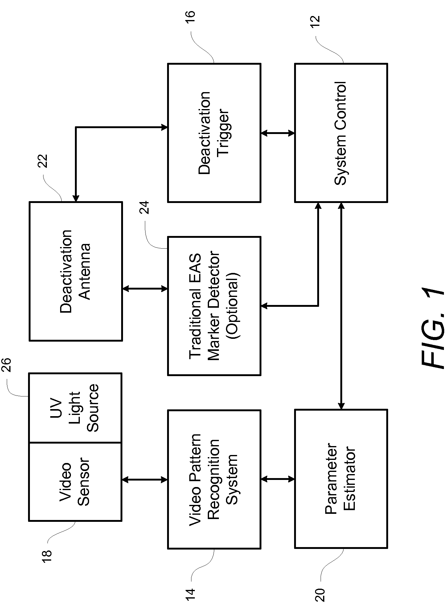
[0031]Embodiments of the present invention include several advantages. For example, the cost of video sensors is quite low due to their use in low-cost optical applications such as webcams, cell phones etc. Also, the cost of video digital signal processing (“DSP”) chip sets used for video pattern recognition applications has dramatically decreased in recent years. This creates an opportunity for a significantly lower cost deactivation triggering technique.

Problems solved by technology

The use of an interrogation field to detect EAS tags has several problems.
Because the EAS response signal can vary significantly from label to label, it is difficult to determine exactly what the predetermined threshold for triggering the EAS deactivation sequence should be.
This variance can cause the deactivation sequence to be triggered when the tag is not in the correct location, thereby causing failures to deactivate (“FTDs”).
Additionally, creating and detecting the magnetic field inside the interrogation area is very expensive, as at least one receiver and one magnetic field generator are required per deactivator.
Also, certain materials may not be suitable for constructing antennas that operate at high frequencies, e.g., laminated, silicon steel does not operate well above about 1 or 2 kHz, requiring the use of more expensive materials for the antenna composition.
Thus, the EAS tag detection circuitry alone can potentially add up to about 25% of the total cost of the deactivator.
Also, the EAS marker signal provides little certainty as to the orientation of the EAS tag.
This inaccuracy further contributes to additional problems with FTDs.

Method used


Image

  • Electronic article surveillance deactivator using visual pattern recognition system for triggering
  • Electronic article surveillance deactivator using visual pattern recognition system for triggering
  • Electronic article surveillance deactivator using visual pattern recognition system for triggering

Examples


Embodiment Construction

[0020]Before describing in detail exemplary embodiments that are in accordance with the present invention, it is noted that the embodiments reside primarily in combinations of apparatus components and processing steps related to implementing a system and method for triggering Electronic Article Surveillance (“EAS”) tag deactivation using visual pattern recognition. Accordingly, the system and method components have been represented where appropriate by conventional symbols in the drawings, showing only those specific details that are pertinent to understanding the embodiments of the present invention so as not to obscure the disclosure with details that will be readily apparent to those of ordinary skill in the art having the benefit of the description herein.

[0021]As used herein, relational terms, such as “first” and “second,”“top” and “bottom,” and the like, may be used solely to distinguish one entity or element from another entity or element without necessarily requiring or impl...


PUM


Abstract

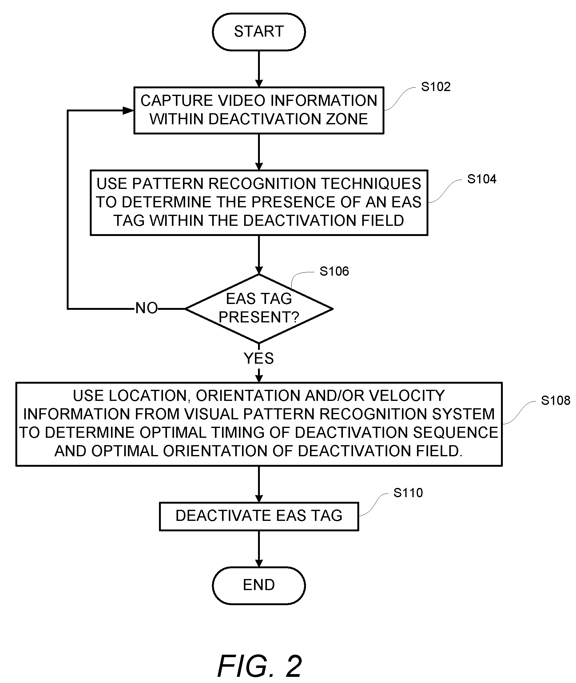
A method, system and electronic article surveillance tag deactivator detect the presence of an electronic article surveillance tag within a deactivation zone. Video of an item within the deactivation zone is captured. The video is evaluated using a pattern recognition technique to determine the presence of an electronic article surveillance tag within the deactivation zone. The electronic article surveillance tag is deactivated.

Description

CROSS-REFERENCE TO RELATED APPLICATION[0001]n / aSTATEMENT REGARDING FEDERALLY SPONSORED RESEARCH OR DEVELOPMENT[0002]n / aFIELD OF THE INVENTION[0003]The present invention relates generally to a method and system for deactivating Electronic Article Surveillance (“EAS”) tags and more specifically to a method and system for deactivating EAS tags using a visual pattern recognition system for triggering.BACKGROUND OF THE INVENTION[0004]Recent advances in automatic article identification technology provide retail and wholesale sales facilities with an improved means for detecting when an article is being shoplifted. One such method, Electronic Article Surveillance (“EAS”), typically includes an EAS detector and EAS devices commonly called labels, tags. markers or transponders. The EAS detector transmits a radio-frequency (“RF”) carrier signal to any EAS device within a certain range of the detector. An active EAS device responds to the carrier signal by generating a response signal of a pre...

Claims


Application Information

Patent Timeline
Patent Type & Authority Patents(United States)
IPC IPC(8): G08B13/14
CPCG08B13/248G06K17/00G06K19/00G08B13/24G08B21/24
Inventor HALL, STEWART E.
Owner SENSORMATIC ELECTRONICS CORP
Learn More