
Method for polarization correction in user equipment

a technology for user equipment and polarization correction, applied in the direction of polarization/directional diversity, transmission monitoring, diversity/multi-antenna system, etc., can solve problems such as the apparent problem of information sent on the vertical polarization

Active Publication Date: 2011-06-21
TELEFON AB LM ERICSSON (PUBL)
View PDF4 Cites 7 Cited by
  • Summary
  • Abstract
  • Description
  • Claims
  • Application Information

AI Technical Summary

Benefits of technology

[0012]The method according to the invention may be implemented with low complexity
[0014]The method may be used for combining MIMO and diversity processing, since it provides means for sorting the polarizations after reception

Problems solved by technology

This presents a problem, since the information that is sent on the horizontal polarization not only is received by the first antenna of the UE, intended for horizontal polarization, but partly also is received by the second antenna of the UE, intended for vertical polarization.
A corresponding problem is apparent for information that is sent on the vertical polarization.

Method used


Image

  • Method for polarization correction in user equipment
  • Method for polarization correction in user equipment
  • Method for polarization correction in user equipment

Examples


Embodiment Construction

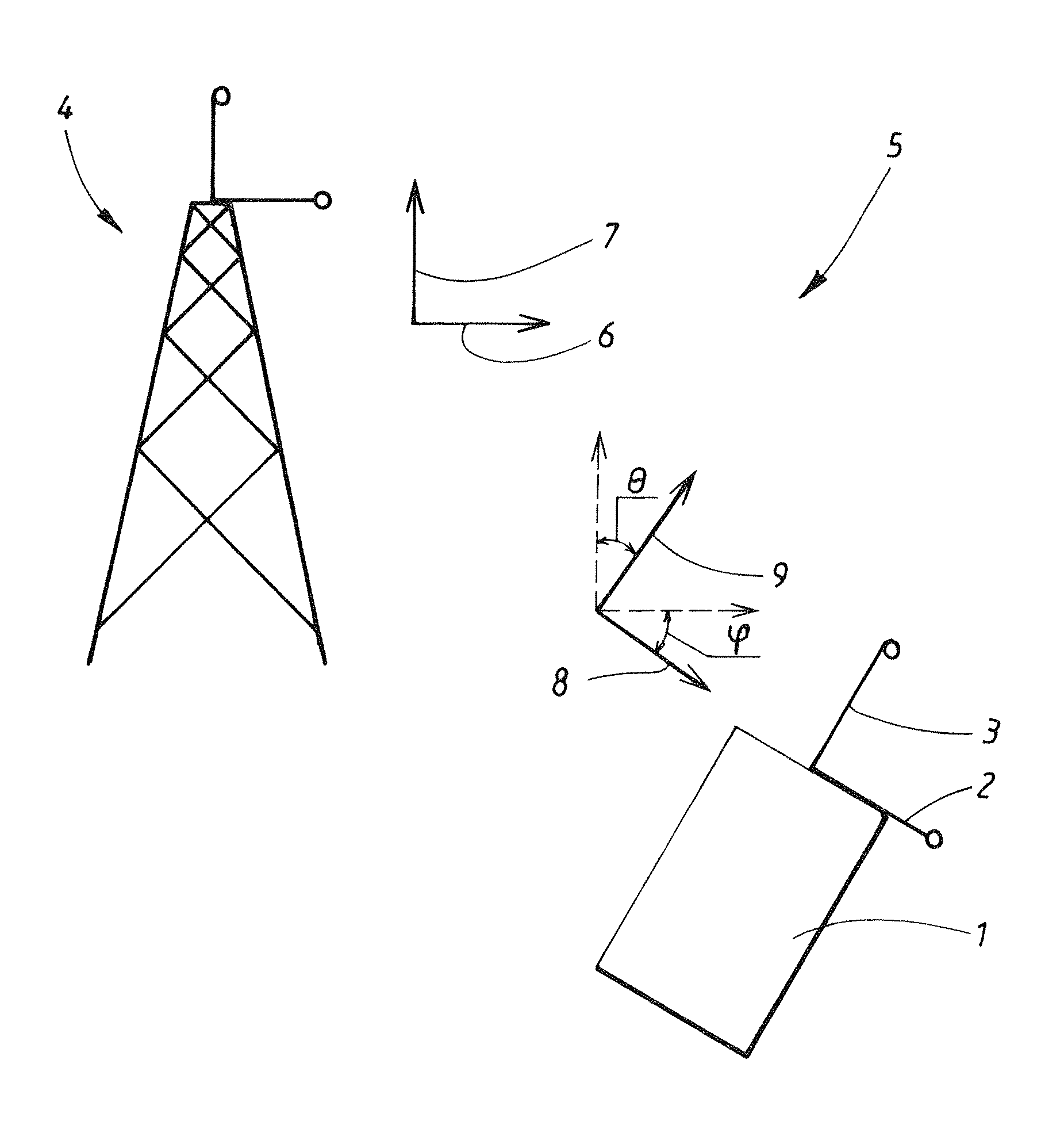
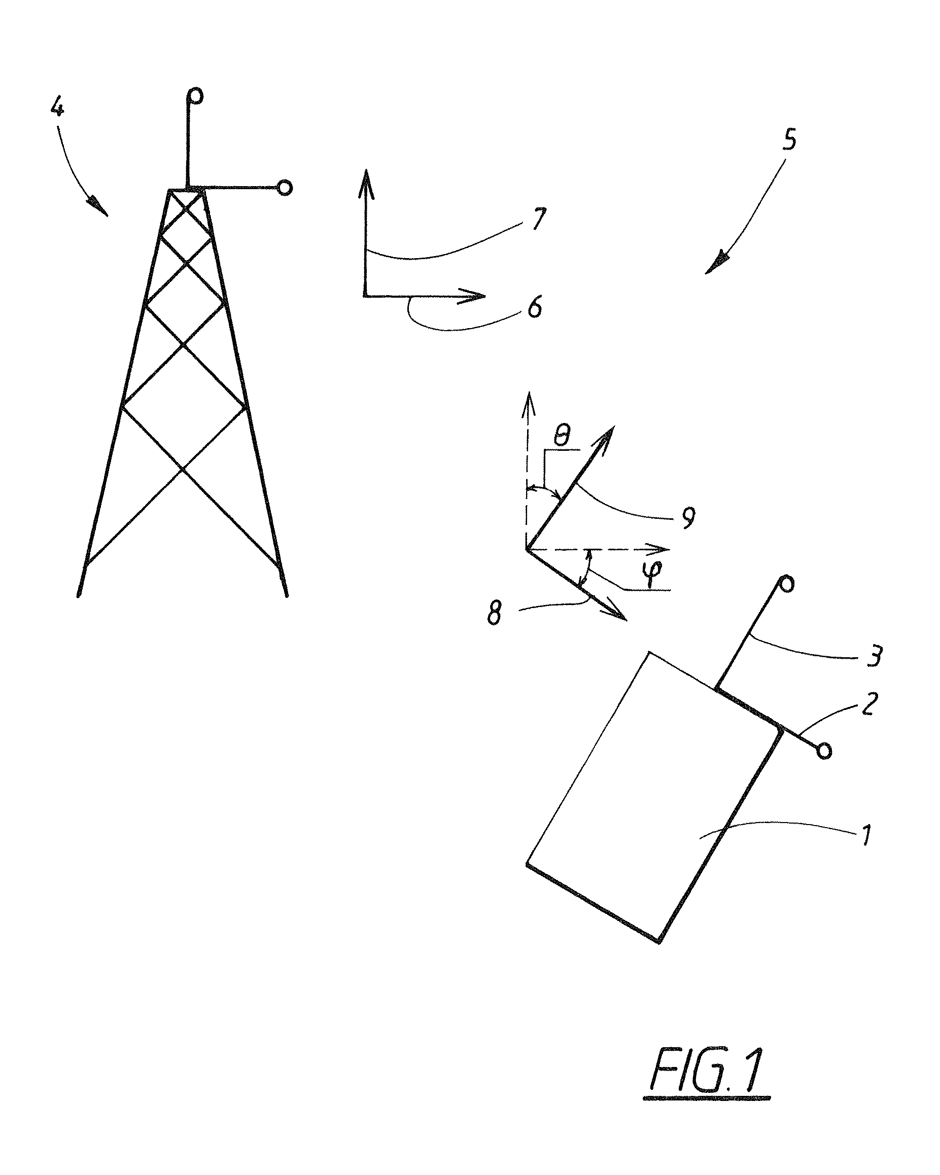
[0018]As shown in FIG. 1, a user equipment 1 (UE) intended for use in a mobile phone network system has a first 2 and second 3 antenna, which antennas 2, 3 are used to receive a message sent on a first and second polarization, in the embodiment example a horizontal and a vertical polarization, from a radio base station 4 (RBS) in an urban environment 5. The UE (1) may for example be a mobile phone or a portable computer. The channel in itself is assumed to be of an ideal nature in this embodiment example, i.e. it does not change the polarization rotation of the signals.

[0019]Due to the UE 1 having a certain rotational position, the first antenna 2 in the UE 1, the polarization orientation of the antenna intended for reception of horizontal polarization, deviates from the polarization orientation of a horizontally transmitted signal 6 by an angle φ. Furthermore, the polarization orientation of the second antenna 3 in the UE 1, the antenna intended for reception of vertical polarizati...


PUM


Abstract

A method and device for compensation of received signal components at a user equipment (UE) used for receiving signal components from a radio base station (RBS). The signal components have at least a first and a second polarization orientation, respectively. The intended reception of the signal component (Yh(n)) having the first polarization deviates from the polarization orientation of the transmitted signal component (Xh(n)) having the first polarization by a first angle (φ), and the intended reception of the signal component (Yv(n)) having the second polarization deviates from the polarization orientation of the transmitted signal component (xv(n)) having the second polarization by a second angle (θ). The method comprises the steps: determining the correlation values (Ryvv, Ryvy, Ryyv, Ryyy) for the received signals (Yh, Yv) at a first time (k) and a second time (m); using these values to determine the deviation angles (φ, θ) performing said compensation using the deviation angles (φ, θ).

Description

TECHNICAL FIELD[0001]The present invention relates to a method for compensation of received signal components at a user equipment (UE) used for receiving signal components from a radio base station (RBS), which signal components have at least a first and a second polarization orientation, respectively, which signal components have been transmitted in a channel, and where the intended reception of the signal component having the first polarization deviates from the polarization orientation of the transmitted signal component having the first polarization by a first angle, and where the intended reception of the signal component having the second polarization deviates from the polarization orientation of the transmitted signal component having the second polarization by a second angle.[0002]The present invention also relates to a device in the form of user equipment (UE) intended for use in a mobile phone network system, having at least a first and second antenna, which antennas are u...

Claims


Application Information

Patent Timeline
Patent Type & Authority Patents(United States)
IPC IPC(8): H04B17/00H04B1/06
CPCH04B7/10H04B7/002
Inventor LINDGREN, ULF
Owner TELEFON AB LM ERICSSON (PUBL)
Learn More