
Bridge forwarding method and apparatus

a forwarding method and forwarding technology, applied in the field of network switching, can solve the problem that the forwarding of vlans by means of bridge forwarding is not supported, and achieve the effect of preventing forwarding loops

Active Publication Date: 2011-06-21
HUAWEI TECH CO LTD
View PDF20 Cites 20 Cited by
  • Summary
  • Abstract
  • Description
  • Claims
  • Application Information

AI Technical Summary

Benefits of technology

The present invention provides a method and apparatus for forwarding frames between different virtual local area networks (VLANs) in a network. The technical effect of this invention is that it allows for cross-VLAN bridge forwarding of frames, which means that frames can be forwarded between different VLANs using a network switch. This is useful for implementing network policies and ensuring that frames are not forwarded in infinite loops. The method includes establishing relationships between ports, VLANs, and VSIs, and searching MAC address forwarding tables to determine the output port and VLAN ID for a given frame. The apparatus includes a forwarding unit that performs these functions and a storing module for storing relationship between combinations of ports and VSIs. The technical effect of this invention is that it allows for more efficient and secure network communication among different VLANs.

Problems solved by technology

In addition, the Ethernet frames can only be broadcasted to one VLAN by means of bridge forwarding, and broadcasting to multiple VLANs by means of bridge forwarding is not supported.

Method used


Image

  • Bridge forwarding method and apparatus
  • Bridge forwarding method and apparatus
  • Bridge forwarding method and apparatus

Examples


embodiment 1

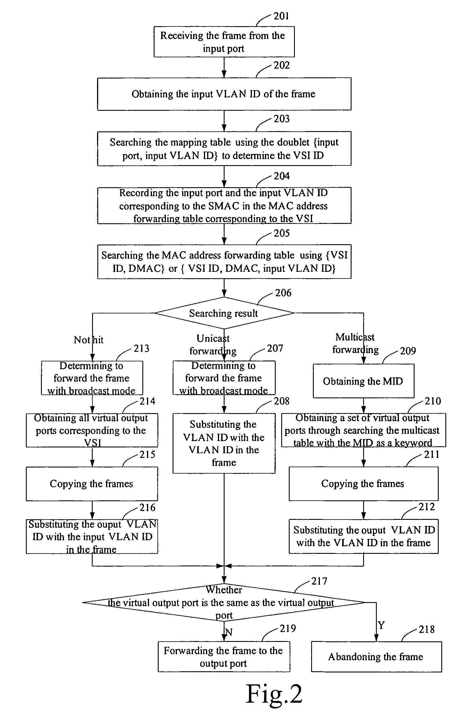
[0051]FIG. 2 is a flow chart illustrating the cross-VLAN bridge forwarding. As shown in FIG. 2, in this embodiment, the cross-VLAN bridge forwarding method mainly includes the steps of:

[0052]Step 201: Receiving the frame from the input port.

[0053]Step 202: Obtaining the input VLAN ID of the frame. Specifically, deciding whether the VLAN ID is carried in the frame, if so, obtaining the VLAN ID of the frame; otherwise, obtaining the default VLAN ID relevant to the input port, and adding the VLAN ID into the frame.

[0054]Step 203: Searching the mapping table by using the doublet {input port, input VLAN ID} to determine the corresponding VSI. Here, the VSI is represented by VSI ID, and the searching result is the corresponding VSI ID. For sake of simplifying the description, one doublet {input port, input VLAN ID} is defined as one input virtual port.

[0055]The mapping table is established to prescribe the relationship between a set of the multiple virtual ports and one VSI, and the forma...

embodiment 2

[0082]The Embodiment 1 describes the bridge forwarding of frames with only one input VLAN ID. In practical terms, however, there is more than one layer of input VLAN ID and output VLAN ID, i.e., there are two layers or more than two layers of input VLAN ID and output VLAN ID. For example, in the applications according to IEEE 802.1 ad standard, two layers of VLAN IDs are carried in the frame. In this kind of application environment, there are two layers of input VLAN ID, so it possibly needs two layers of output VLAN ID. In this embodiment, a number of {input port, input outer-layer VLAN, input inner-layer VLAN} correspond to one VSI, i.e., a number of {input port, input outer-layer VLAN, input inner-layer VLAN} is bound with one VSI.

[0083]The main procedure of bridge forwarding of frames with two layers of input VLAN ID and output VLAN ID is described in detail with reference to FIG. 3.

[0084]Step 301: Receiving the frame from the input port.

[0085]Step 302: Determining whether the V...


PUM


Abstract

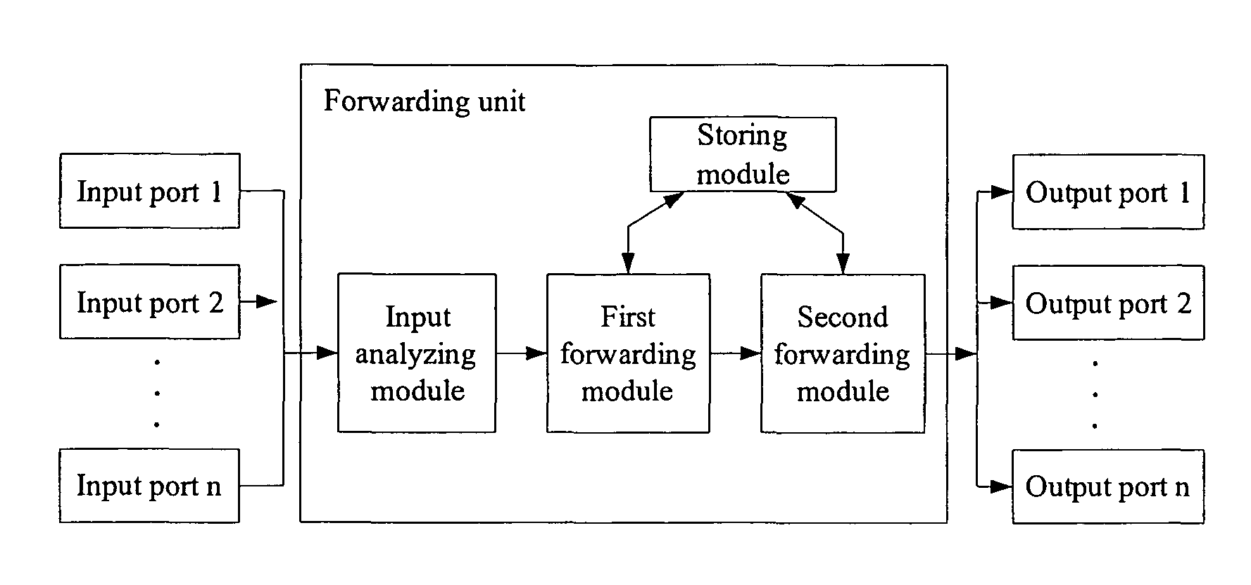
A bridge forwarding method comprises: receiving a frame from an input port, obtaining the input VLAN ID and a destination MAC address of the frame; determining an output port and an output VLAN ID of the frame, and forwarding the frame according to the output port and the output VLAN ID. A bridge forwarding apparatus includes at least one output port used for receiving a frame from more than one VALN, at least one output port used for transmitting the frame to more than one VALN and a forwarding unit, the forwarding unit obtains the input VLAN ID and the destination MAC address in the frame, determines the output port and the output VLAN ID of the frame, and outputs the frame to the corresponding output port. The method and the apparatus of this invention can realize the bridge forwarding of the Ethernet frames between multiple VLANs.

Description

FIELD OF THE TECHNOLOGY[0001]The present invention relates to the network switching technical field. More particularly, the present invention relates to a bridge forwarding method and a bridge forwarding apparatus.BACKGROUND OF THE INVENTION[0002]There are two approaches for forwarding the frames of the Ethernet at present: Layer 2 Ethernet bridge and Layer 3 IP route. The Layer 2 Ethernet bridge refers to a method for searching the Destination Media Access Control (MAC) address forwarding table by using the MAC address to obtain the exit information and forwarding the data packets according to the exit information. The Layer 3 IP route is a method for searching the routing table by using the destination IP to obtain the exit information and forwarding the data packets according to the exit information. The MAC address forwarding table is obtained through the self-learning of source MAC (SMAC) address or statically configured by software.[0003]At present, as defined in the Ethernet ...

Claims


Application Information

Patent Timeline
Patent Type & Authority Patents(United States)
IPC IPC(8): H04L12/56
CPCH04L12/4666
Inventor DU, WENHUA
Owner HUAWEI TECH CO LTD
Learn More