
Diesel particulate control

a technology of particulate control and diesel, which is applied in the direction of arsenic compounds, silicon compounds, separation processes, etc., can solve the problems of sulfate formation (particulates), deactivation of the catalytic soot filter, and lack of desired durability of the catalyst soot filter, so as to achieve the effect of high efficiency of pt—ce fuel borne catalysts and improved efficiency

Inactive Publication Date: 2011-06-21
CLEAN DIESEL TECHNOLOGIES
View PDF14 Cites 8 Cited by
  • Summary
  • Abstract
  • Description
  • Claims
  • Application Information

AI Technical Summary

Benefits of technology

[0012]It is an object of this invention to provide new insights on mechanistic aspects for very high efficiency of Pt—Ce fuel borne catalysts and to employ them in the design of particulate filters with improved efficiency.
[0013]It is another object of the invention to provide particulate filters with improved efficiency in terms of regeneration characteristics.
[0014]It is another object of the invention to provide particulate filters with improved regeneration characteristics, which could preferably retain increased levels of ultrafine particles without disadvantageous sacrifices in fuel economy or DPF size.

Problems solved by technology

Unfortunately, diesel engines contribute significantly to urban and global air pollution through the emissions, particularly soot or carbon particulates (PM) and NOx.
Unfortunately, catalyzed soot filters lack the desired durability, and the presence of SO2 further leads to sulfate formation (particulates) and deactivation of the catalyzed soot filter.
Though enough NO is present in the feed gas, the rate of NO oxidation to NO2 over Ce or Ce—Fe fuel borne catalysts is not efficient and therefore the more powerful oxidant (NO2) cannot be extensively generated, leading to insignificant NO impact on soot oxidation.
However most of these studies are performed in loose contact mode and not with CeO2 and soot in tight contact and NO+O2 as an oxidant.

Method used


Image

  • Diesel particulate control
  • Diesel particulate control
  • Diesel particulate control

Examples


Embodiment Construction

[0046]The invention provides improvements in controlling the emission of particulates form diesel engines. It does so based on testing outlined in the Examples below and with the implementation of new diesel particulate filter / fuel additive combinations.

[0047]The invention is based on discoveries most easily observable with low sulfur content fuels, whereas they are effectively utilized in all fuels suitable for diesel use, including those with up to about 500 ppm sulfur. The term “fuel” is thus intended to include all of those fuels effective for operating diesel engines. The fuel can contain detergent (e.g., 50-300 ppm), lubricity additive (e.g., 25 to about 500 ppm) and other additives, as desired.

[0048]Among the fuels suitable for use in the invention are those which typically comprise a fossil fuel, such as any of the typical petroleum-derived fuels including distillate fuels. A fuel can be one or a blend of fuels selected from the group consisting of: distillate fuels, includi...


PUM

PropertyMeasurementUnit
exhaust gas temperaturesaaaaaaaaaa
temperatureaaaaaaaaaa
ignition temperatureaaaaaaaaaa

Abstract

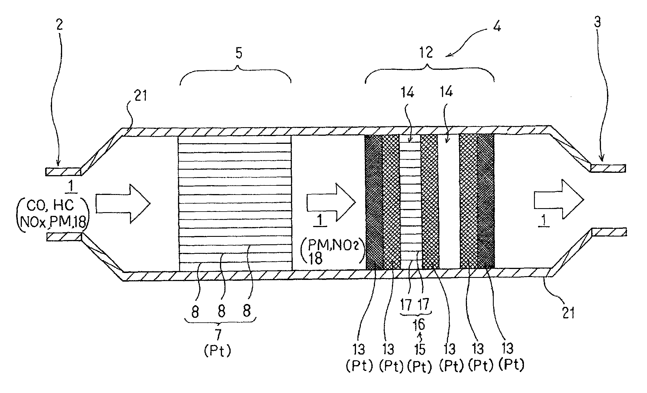
A method and apparatus are provided for reducing emissions of particulates from diesel engines. Exhaust is passed through a diesel particulate filter having at least two stages comprised of (a) a catalyst section having a platinum group metal catalyst on contact surfaces within the catalyst section and (b) a filter section comprised of passages effective to remove particulates from a moving stream of combustion gases generated by combusting the fuel in the engine and holding them therein to permit their oxidation. Carbon removal is enhanced by utilizing levels of platinum group metal composition, cerium compositions, fuels and / or optional chemical enhancers to generate NO2 in the catalyst section in amounts sufficient to form cerium nitrates in the filter section. The cerium oxide is associated with and maintains dispersion of the platinum in the filter section, and the cerium nitrates are available at the surface and within the soot particles to provide enhanced soot oxidation at a lower balance point.

Description

RELATED APPLICATIONS[0001]This application claims priority to applicant's U.S. Provisional Patent Application No. 60 / 747,580, filed May 18, 2006.BACKGROUND OF THE INVENTION[0002]The invention relates to improvements in controlling the emission of particulates from diesel engines and provides methods and apparatus to that end.[0003]Diesel engines are the most preferred for heavy-duty applications and light-duty trucks due to their high torque and superior fuel economy. By virtue of their fuel economy they also result in decreased CO2 emissions as compared to other engines. Unfortunately, diesel engines contribute significantly to urban and global air pollution through the emissions, particularly soot or carbon particulates (PM) and NOx. There is a recognized tradeoff between PM and NOx—when one is decreased, the other tends to increase.[0004]Particulates (soot) can be collected on a filter, and active and passive filter regeneration strategies are being used in practice to burn soot....

Claims


Application Information

Patent Timeline
Patent Type & Authority Patents(United States)
IPC IPC(8): B01D50/00F01N3/10
CPCB01D53/90F01N13/0097C10L1/14C10L10/02F01N3/0231F01N3/0253F01N3/029F01N3/035F01N3/206F01N3/2066B01D53/944B01D2255/1021B01D2255/206C10L1/1814C10L1/1881C10L1/1886C10L1/189C10L1/305F01N2430/04F01N2610/01F01N2610/02F01N2610/03Y02T10/24Y02T10/12B01D53/94F01N3/021F01N3/10
Inventor MAKKEE, MICHIELKAMASAMUDRAM, KRISHNACOPAN, WALTER G.
Owner CLEAN DIESEL TECHNOLOGIES
Learn More