Device for a remote monitoring the state of at least a single-pole surge protection device

a surge protection device and remote monitoring technology, applied in the direction of resistors, emergency protective arrangements for limiting excess voltage/current, non-adjustable resistors, etc., can solve the problem that the signalling function does not allow the rotation of the varistor insert through 180°, and the cost is increased

Inactive Publication Date: 2011-06-14
KIWA SPOL
View PDF8 Cites 0 Cited by
  • Summary
  • Abstract
  • Description
  • Claims
  • Application Information

AI Technical Summary

Benefits of technology

[0013]The device utilizes a simple, reliable and durable arrangement with a signalling plate of a low weight and a sufficient rigidity which enables sensing the state of some surge protector poles by one signalling plate and one switch. There is no spring or another element to act on the signalling plate in the faultless state which would hold the signalling plate in the defined position. Because the signalling plate is very light, it cannot cause a change of the switch state by its weight in any position of the bracket. By means of this, is reached a significant simplification of the construction and a reduction of the manufacturing costs.
[0014]According to one preferred embodiment, the suspended positioning elements are in the bracket placed in a position in which they bear by their indicating ends on a sliding member in associated slide-in protective members both in the normal position and also in the turned through 180° position, thus there occurs no change in the device properties while angular rotation of the slide-in protective member in the bracket.
[0015]According to one preferred embodiment there is a positioning element, fitted with a flange on its other end, fitted with a cavity in which there is a pressure spring positioned, which is by one end based on the bottom of the cavity in the positioning element and it leans against the wall of the bracket by its other end, which is a simple, reliable and durable solution.
[0018]To prevent sliding the slide-in protective member with wrong protective properties into the bracket, it is preferred that the slide-in protective members of different protective properties are fitted with mutually different first identifiers, whereas the bracket is for each pole of the surge protector fitted with the second identifier which contains identification elements corresponding only to the identification elements on the first identifiers of the slide-in protective members with the corresponding protective properties.

Problems solved by technology

However, for economic reasons there are decreasingly used solutions where each pole of the surge protector is fitted with a switch and there are increasingly used solutions where more poles of the surge protector have one shared switch.
The disadvantage of this solution, other than higher costs, consists particularly in increased space demands which represent a disadvantage particularly in surge protectors with a lower number of poles.
The disadvantage of this solution is that it is bound to the particular arrangement of the bracket according to DE 100 01 667 C1.
Another disadvantage is that the signalling function does not allow rotation of the varistor insert through 180° which is given by assymetric positioning of the indicating component of the varistor insert.
Another disadvantage consists in a permanent action of the hinged lever on the switch, until comes to a disconnection of any of the protective members of the surge protector from the main supply which is demanding on a regular and long-durable pressure setting of the hinged lever onto the switch.
The disadvantage of this solution consists in that it needs a coordinated action of a number of springs, by means of which this solution is sensitive to manufacturing variations in the system of used elements and also sensible to a contingent time-stability of the parameters of particular springs.
It results in usage limitation of one switch for only a small number of surge protector poles, while concurrent demand on relatively heavy duty design of the hinged lever by virtue of acting forces magnitude and possible deformations, which represents another drawback of this solution.

Method used


Image

  • Device for a remote monitoring the state of at least a single-pole surge protection device
  • Device for a remote monitoring the state of at least a single-pole surge protection device
  • Device for a remote monitoring the state of at least a single-pole surge protection device

Examples


embodiment

OF EMBODIMENT

[0022]Reference will now be made to embodiments of the invention, one or more examples of which are shown in the drawings. Each embodiment is provided by way of explanation of the invention, and not as a limitation of the invention. For example features illustrated or described as part of one embodiment can be combined with another embodiment to yield still another embodiment. It is intended that the present invention include these and other modifications and variations to the embodiments described herein.

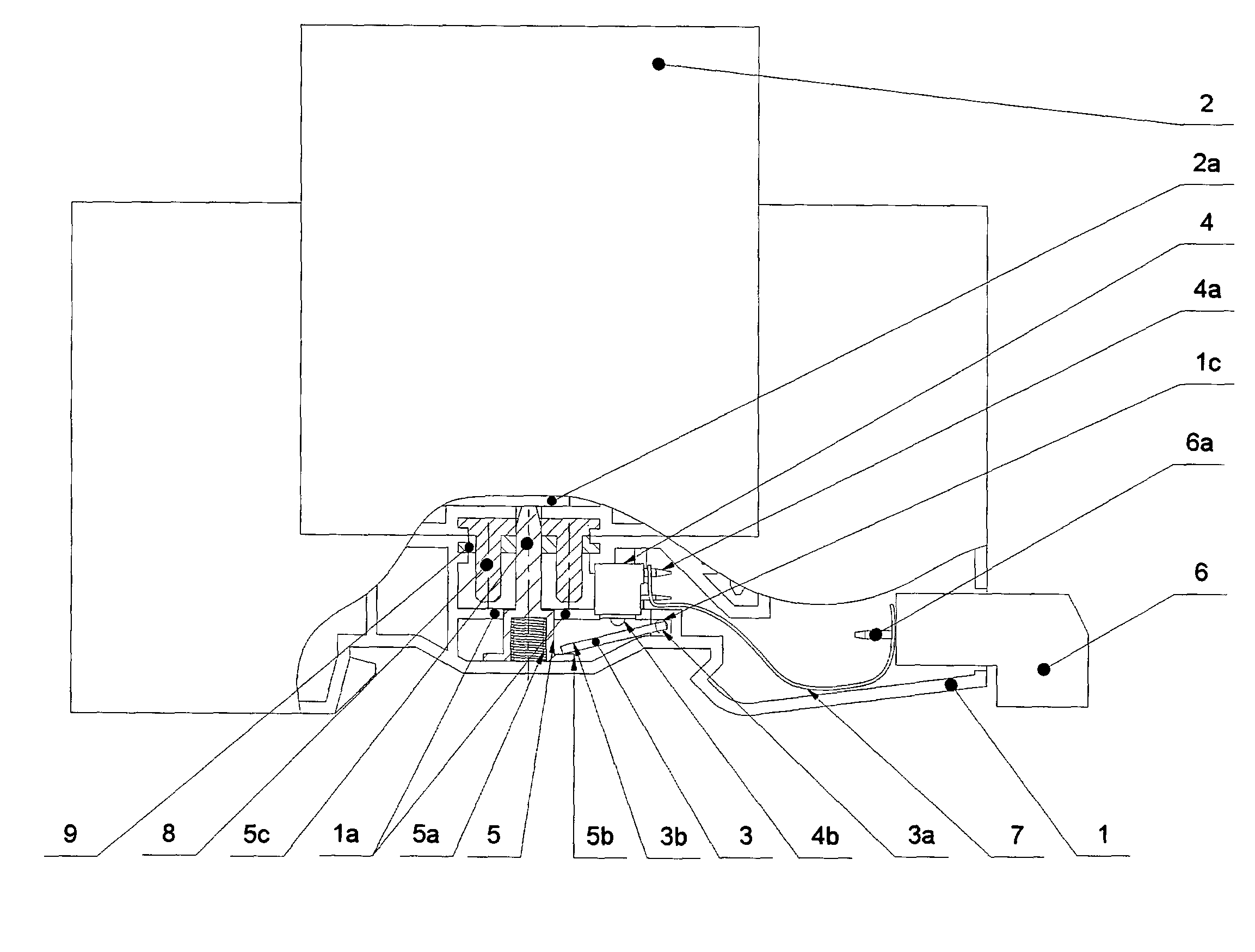
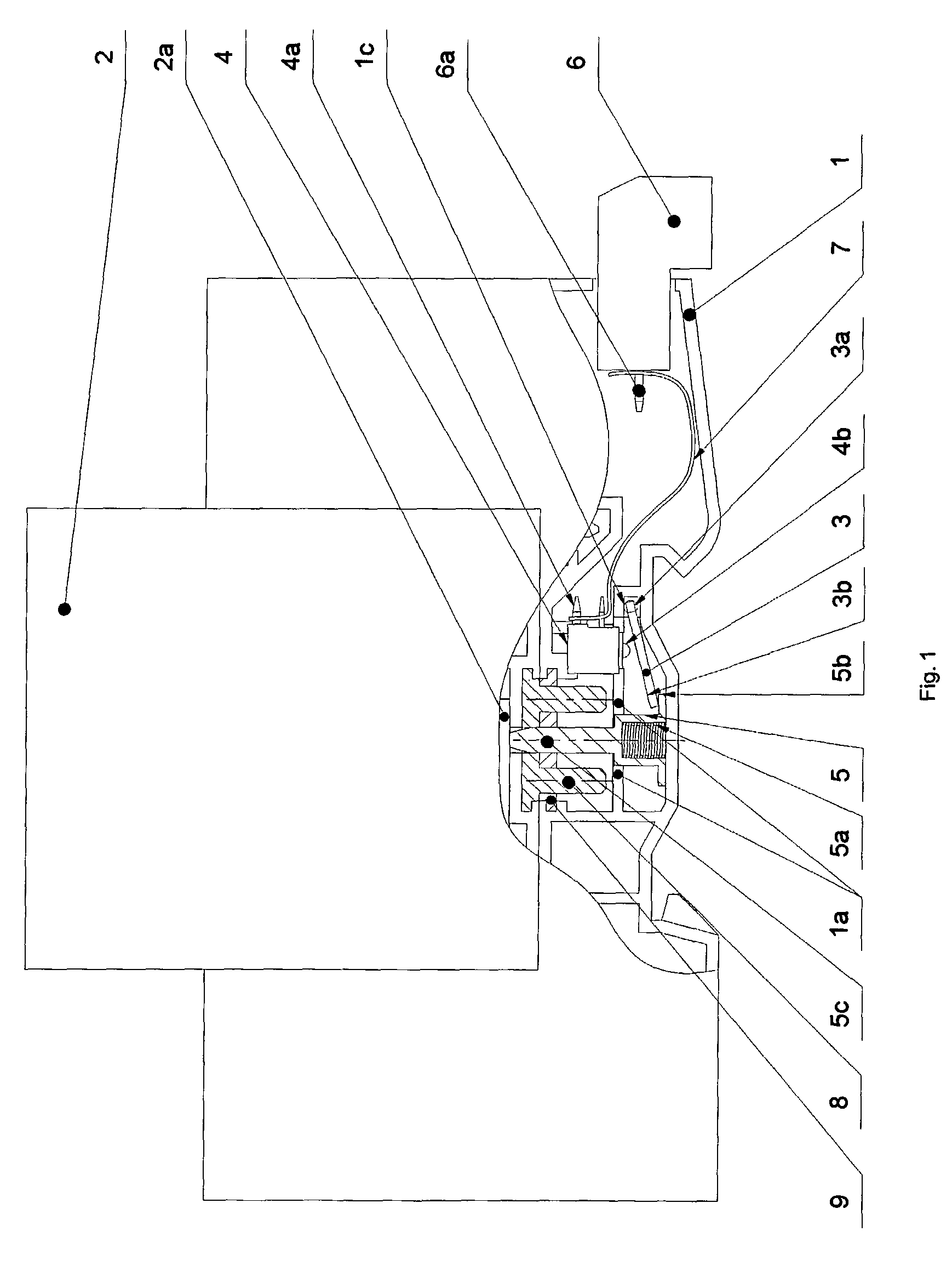
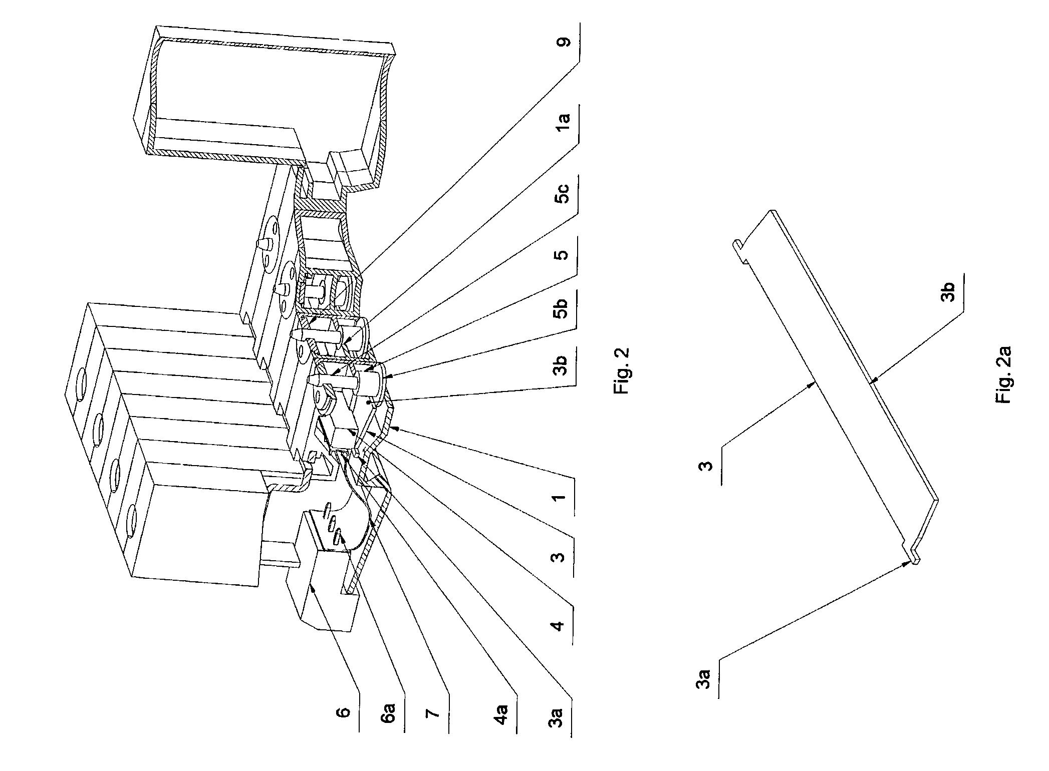
[0023]A device for a remote monitoring the state of at least a single-pole surge protector comprises a U-shaped bracket 1. There is one slide-in protective member 2 for each pole of the surge protector slid into the bracket 1. The bracket 1 can be formed as one body or it can be made as a number of bodies (e.g. one body for each surge protector pole) connected into one piece by, for instance rivets or another appropriate connecting members.

[0024]The slide-in protective...


PUM


Abstract

The invention relates to a device for a remote monitoring the state of at least a single-pole surge protection which consists of a bracket (1) and at least one slide-in protective member (2) whereas the bracket (1) and also the slide-in protective members (2) are fitted with mechanical devices for detecting the status change of each of the slide-in protective members (2) and the bracket (1) is further fitted with devices for the status change of the switch (4) on the basis of a status change of some of the slide-in protective members (2) whereas the switch (4) is fitted with devices for connecting to the remote conduit of the status change of the switch (4) signal.

Description

TECHNICAL FIELD[0001]The invention relates to a device for a remote monitoring the state of at least a single-pole surge protection device (surge protector) which consists of a bracket and at least one slide-in protective member whereas the bracket and also the slide-in protective members are fitted with mechanical devices for detecting the status change of each of the slide-in protective members, and the bracket is further fitted with devices for the status change of the switch on the basis of a status change of some of the slide-in protective members whereas the switch is fitted with devices for connecting to the remote signal conduit of the switch status change.BACKGROUND ART[0002]The protective member's status of surge protectors can be, as a rule, detected optically directly on the protective member. However, there is very often a requirement for a remote detection of the surge protector's status, or in particular for on a remote information transfer on the surge protector's st...

Claims


Application Information

Patent Timeline
Patent Type & Authority Patents(United States)
IPC IPC(8): H02H9/06H02H3/22
CPCH01C7/12H01T1/12H01C7/123
Inventor T
Owner KIWA SPOL
Why Eureka
Try Eureka