
In-situ lubrication of sliding electrical contacts

a technology of electrical contacts and in-situ lubrication, which is applied in the direction of lubricant compositions, petroleum industry, base materials, etc., can solve the problems of affecting the development of a superconducting homopolar motor (schpm) for ship propulsion, affecting the minimum required wear length of brushes, and generally providing insufficient wear protection for some important applications

Inactive Publication Date: 2011-06-14
UNIV OF FLORIDA RES FOUNDATION INC
View PDF10 Cites 2 Cited by
  • Summary
  • Abstract
  • Description
  • Claims
  • Application Information

AI Technical Summary

Problems solved by technology

Greases can contaminate the product of the system being lubricated, making it undesirable for food processing, and grease and oil outgas in a vacuum preclude their use in space applications.
Conventional solid lubricants currently available generally provide insufficient wear protection for some important applications.
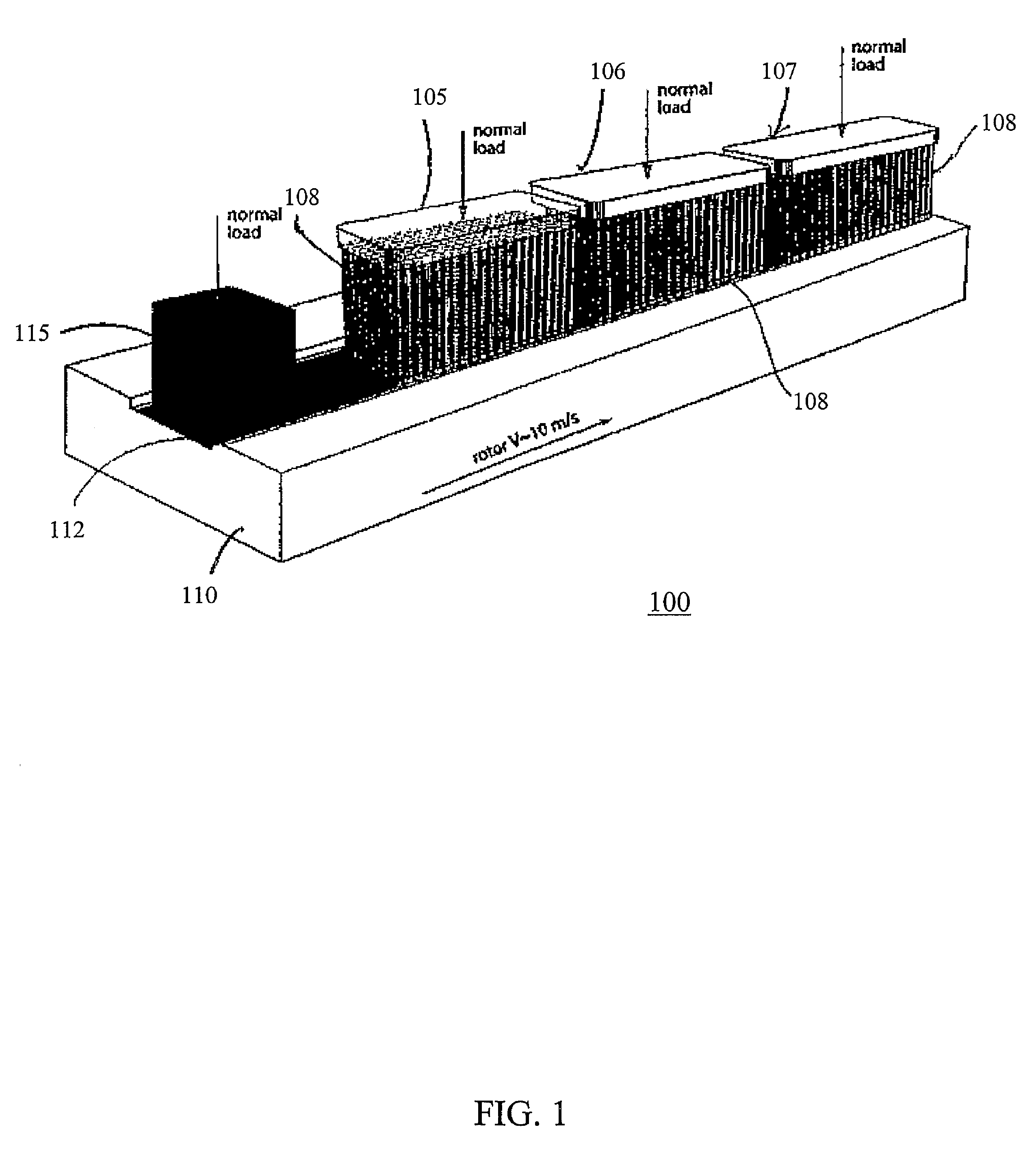
For example, even with the use of available solid lubricants to reduce wear rates and friction, current efforts to develop a Superconducting Homopolar Motor (SCHPM) for ship propulsion have been hampered by excessive wear in the brush system which conducts high electrical currents from the rotor to the stator.
Since the brushes of SCHPMs are known to wear during use, designers typically must base design decisions on an assumed wear rate for the brushes based on past experience and projected technology development, which generally results in a minimum required wear length for the brushes.
In order to be able to achieve the required wear rates, contact forces need to be kept very low, on the order of about 3 to 4 N. Unfortunately, for electrical contacts between bulk solids, low contact forces can result in high contact resistance as well as excessive heating and losses at the interface.
The difficulty is sometimes addressed by the use of multifilament wire brushes, in an attempt to achieve satisfactory contact resistance at these low forces.
However, when multifilament brushes are used in the high magnetic fields and high current densities of the SCHPM, electromagnetic forces on the individual filaments of the brush are typically high enough to distort the filaments, often quite significantly, thus changing the true contact force and altering the brush wear rate in some sections of the motor.

Method used


Image

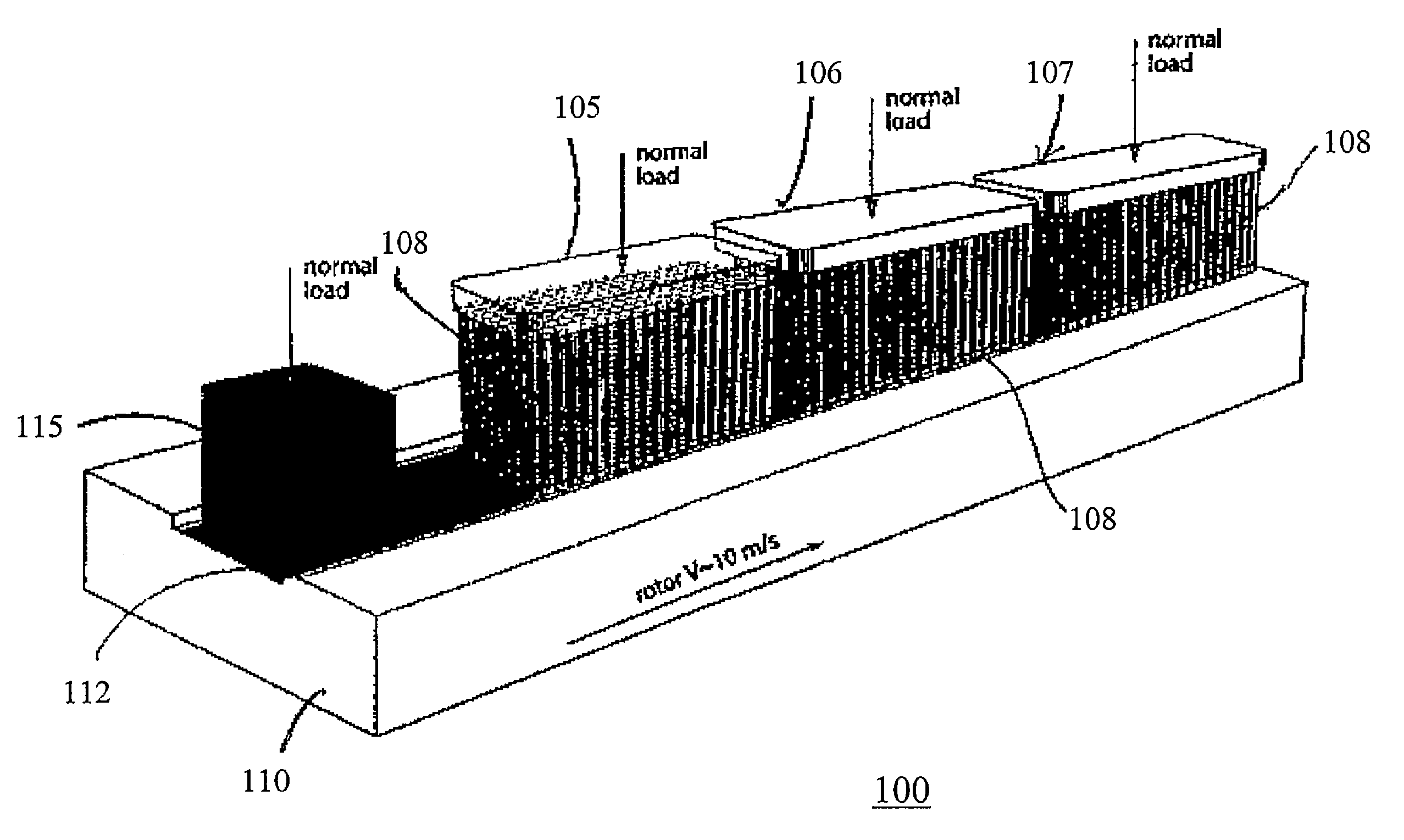
  • In-situ lubrication of sliding electrical contacts
  • In-situ lubrication of sliding electrical contacts
  • In-situ lubrication of sliding electrical contacts

Examples


example

[0028]The present invention is further illustrated by the following example. The example, however, is only for the purpose of illustrating aspects of the invention and should not be construed as limiting the scope or content of the invention in any way.

[0029]Referring to FIGS. 3A and 3B, a demonstration of the in situ solid lubrication of self-mated copper contacts was performed on a high-speed rotating pin-on-disk tribometer. The experimental setup is illustrated in FIG. 3A. Corresponding results are presented graphically in FIG. 3B. The copper disk 302 shown was sanded to an initial surface roughness of Ra˜0.15 μm and had a diameter of approximately 50 mm. The copper pin 304 had a diameter of approximately 6 mm and was loaded against the copper disk 302 by a dead weight load of 5N. The disk 302 was rotated at a constant angular speed resulting in a sliding speed at the contact of 1.5 m / s. The solid lubricant pin 306 was unloaded and could be manually brought into contact as needed...


PUM

PropertyMeasurementUnit
contact forcesaaaaaaaaaa
thickaaaaaaaaaa
diameteraaaaaaaaaa

Abstract

A method for in-situ solid lubrication of sliding electrical contacts includes the steps of providing a device having a movable electrically conductive first member and an electrically conductive second member, the first and second member being in electrical contact at a slideable electrical contact, and automatically applying an electrically conductive solid lubricant transfer film to the slideable electrical contact during operation of the device. The applying step can be a deposition of the electrically conductive solid lubricant transfer film on a surface of the first member, wherein the electrically conductive solid lubricant transfer film is carried by movement of the first member to the electrical contact.

Description

CROSS-REFERENCE TO RELATED APPLICATIONS[0001]This application is a §371 national stage entry of International Application No. PCT / US2006 / 008152, filed Mar. 8, 2006, which claims priority to U.S. Provisional Application No. 60 / 659,719, filed Mar. 8, 2005, both of which are hereby incorporated by reference.FIELD OF THE INVENTION[0002]The invention relates to electrically conductive solid lubricant comprising transfer films including a solid lubricant, and at least one soft metal, and methods for applying the same during operation of systems having sliding electrical contacts.BACKGROUND OF THE INVENTION[0003]One of the primary goals of lubricants is obtaining low friction. Solid lubrication offers many benefits over conventional oil-based hydrodynamic and boundary lubrication. Solid lubrication systems are generally more compact and less costly than oil lubricated systems since pumps, lines, filters and reservoirs are usually required in oil lubricated systems. Greases can contaminate ...

Claims


Application Information

Patent Timeline
Patent Type & Authority Patents(United States)
IPC IPC(8): H01R39/56C10M103/04
CPCC10M103/00C10M103/02H01R43/14H01R39/56H01R39/58C10M2201/041C10M2201/06C10N2210/01C10N2210/03C10N2240/20C10N2240/202H01R39/24C10N2230/60C10N2010/06C10N2030/60C10N2010/02C10N2040/14C10N2040/17
Inventor ZIEGERT, JOHN C.SAWYER, WALLACE G.BURRIS, DAVID L.
Owner UNIV OF FLORIDA RES FOUNDATION INC
Learn More