
Partial load enabled falling film evaporator and method for operating a partial load

a technology of falling film evaporator and partial load, which is applied in the direction of distillation, separation machine, separation, etc., can solve the problems of inadequately suited to part-load operation, poor controllability of the device, and heated falling film evaporators

Inactive Publication Date: 2011-06-14
UHDE GMBH
View PDF21 Cites 2 Cited by
  • Summary
  • Abstract
  • Description
  • Claims
  • Application Information

AI Technical Summary

Benefits of technology

The invention aims to solve the problems of existing falling film evaporators by providing a better design for part-load operation.

Problems solved by technology

The technical problem addressed in this patent is the inability of falling film evaporators to operate efficiently at part-load, meaning they are not suitable for quick-acting control actions. This is due to the condensation behavior of the heating fluid and the difficulty in removing the gas from the evaporator. The patent proposes a new design that overcomes these limitations.

Method used


Image

  • Partial load enabled falling film evaporator and method for operating a partial load
  • Partial load enabled falling film evaporator and method for operating a partial load
  • Partial load enabled falling film evaporator and method for operating a partial load

Examples


Embodiment Construction

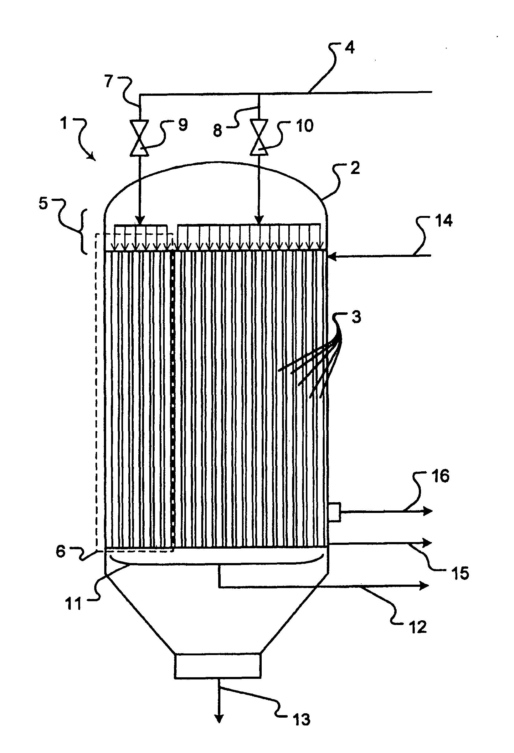
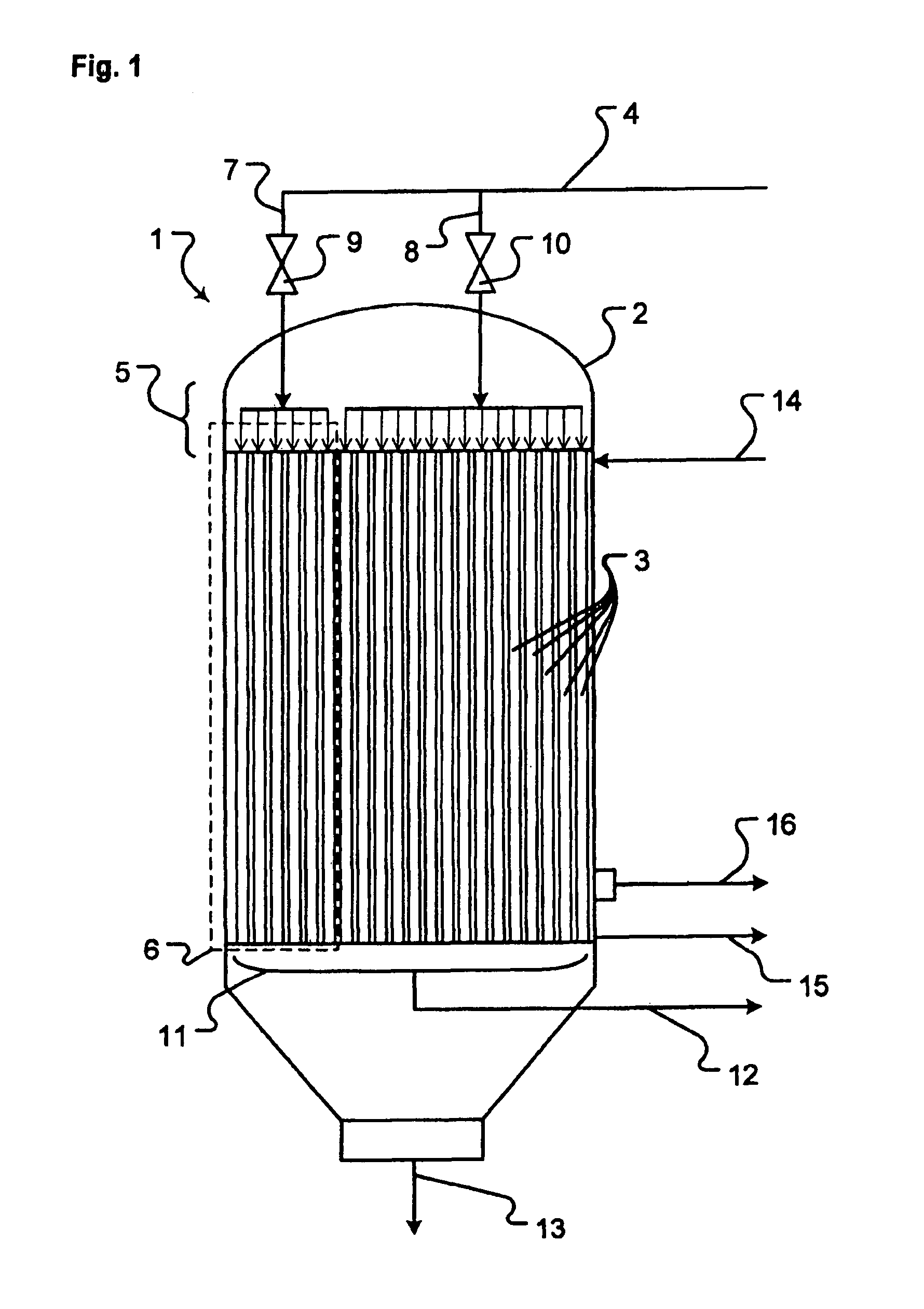
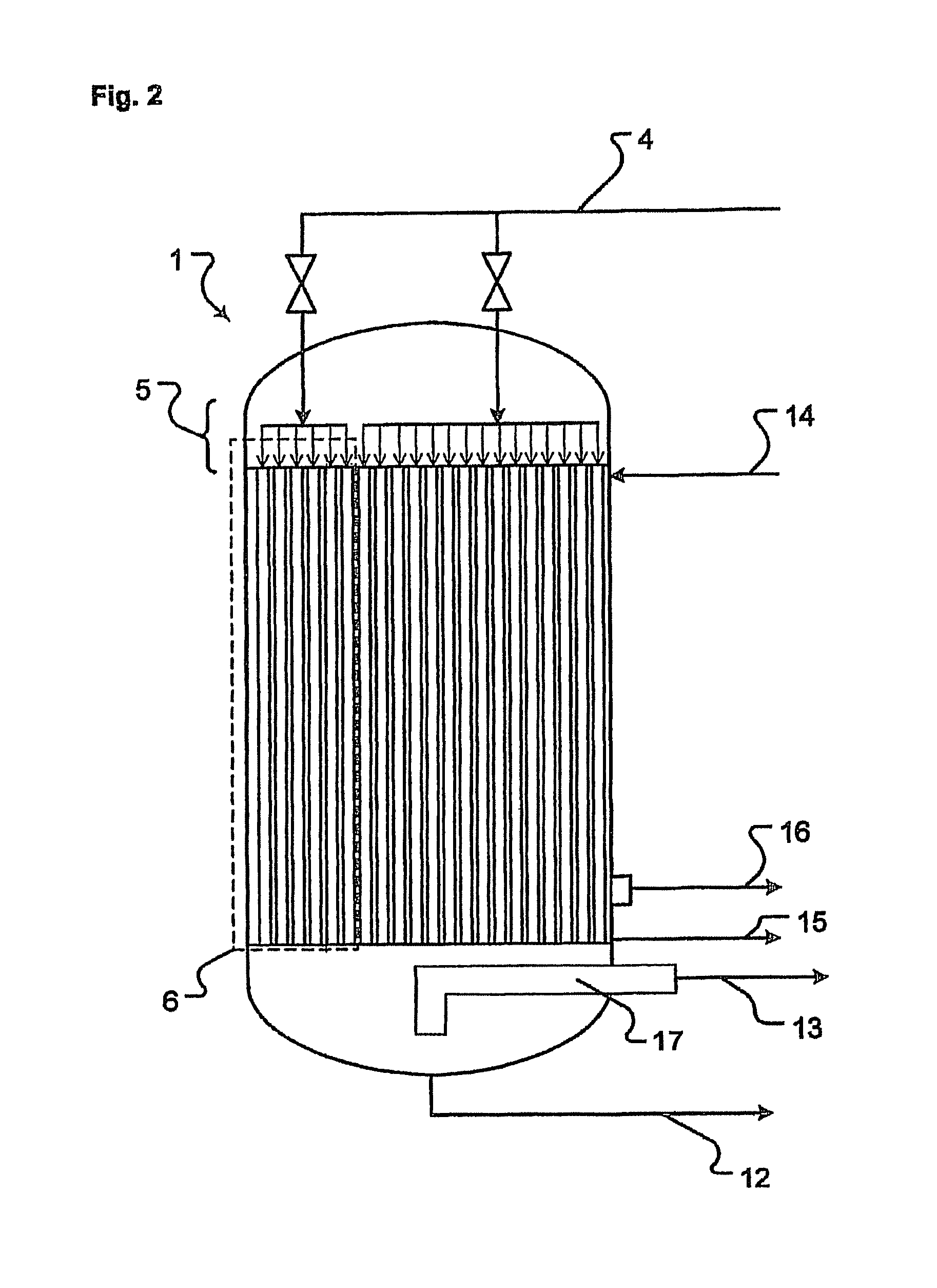
[0024]The aim of the invention is achieved by a partial load enabled falling film evaporator with an external outer shell. The device includes a number of tubes, the internal side of which has a liquid film flowing downwards, comprising an internal chamber. Upper end devices for distributing the liquid to the individual tubes are also included, as are lower end devices for collecting residual liquid and vapor. A vapor extracting device for withdrawing the vapor forming inside the tubes and a device for withdrawing the non-evaporated portion of the liquid inside the tubes are also provided. Hydraulic devices are linked to the internal chamber of the tubes. Partitions are provided that separate the internal chamber of the tubes and the hydraulic devices for distributing and collecting fluids from the space enclosing the tubes. A device for feeding a mixture of the gas and vapor to a chamber enclosing the external side of the tubes is provided, along with a device for withdrawing conde...


PUM


Abstract

The invention relates to a falling film evaporator, which is fitted with a liquid distributor which is divided into segments, such that it is possible to charge only a limited number of evaporator tubes with liquid and the evaporator can be operated in an optimum manner even with a partial load. The invention also relates to a method for operating said falling film evaporator, the aim of which is to transfer heat, which is released when a gas-vapor mixture is condensed, to a liquid which is to be evaporated at least partially. It would be useful to use said falling film evaporator thus fitted in heat recuperation systems such as those used in the production of 1,2 dichloroethane.

Description


Claims


Application Information

Patent Timeline
Owner UHDE GMBH
Learn More