
Substrate processing apparatus

a processing apparatus and substrate technology, applied in the direction of conveyors, electrical devices, thin material processing, etc., can solve the problems of affecting the cost of processing substrates, the price of devices, and the cost of electronic devices manufacturing costs

Inactive Publication Date: 2011-06-14
BOOKS AUTOMATION US LLC
View PDF68 Cites 80 Cited by
  • Summary
  • Abstract
  • Description
  • Claims
  • Application Information

AI Technical Summary

Benefits of technology

The substrate processing apparatus described in this patent text has a transport chamber with a linear array of substrate holding modules and a movable substrate transport. The transport chamber can hold an isolated atmosphere and has multiple linear transport paths between its walls. The substrate transport is capable of moving the substrate along these paths using a transporter that interfaces with the chamber. The transport chamber can also have different transport tubes with different transport paths for substrate transfer. The technical effects of this design include improved substrate processing efficiency and flexibility in substrate transfer between different transport paths.

Problems solved by technology

One of the factors affecting consumer desire for new electronic devices naturally is the price of the device.
A significant portion of the manufacturing costs for electronic devices is the cost of producing the electronics which starts with the manufacturing and processing of semi-conductor substrates such as used in manufacturing electronic components, or panels used for making displays.
The cost of processing substrates is affected in part by the cost of the processing apparatus, the cost of the facilities in which the processing apparatus are housed, and in large part by the throughput of the processing apparatus (which has significant impact on unit price).
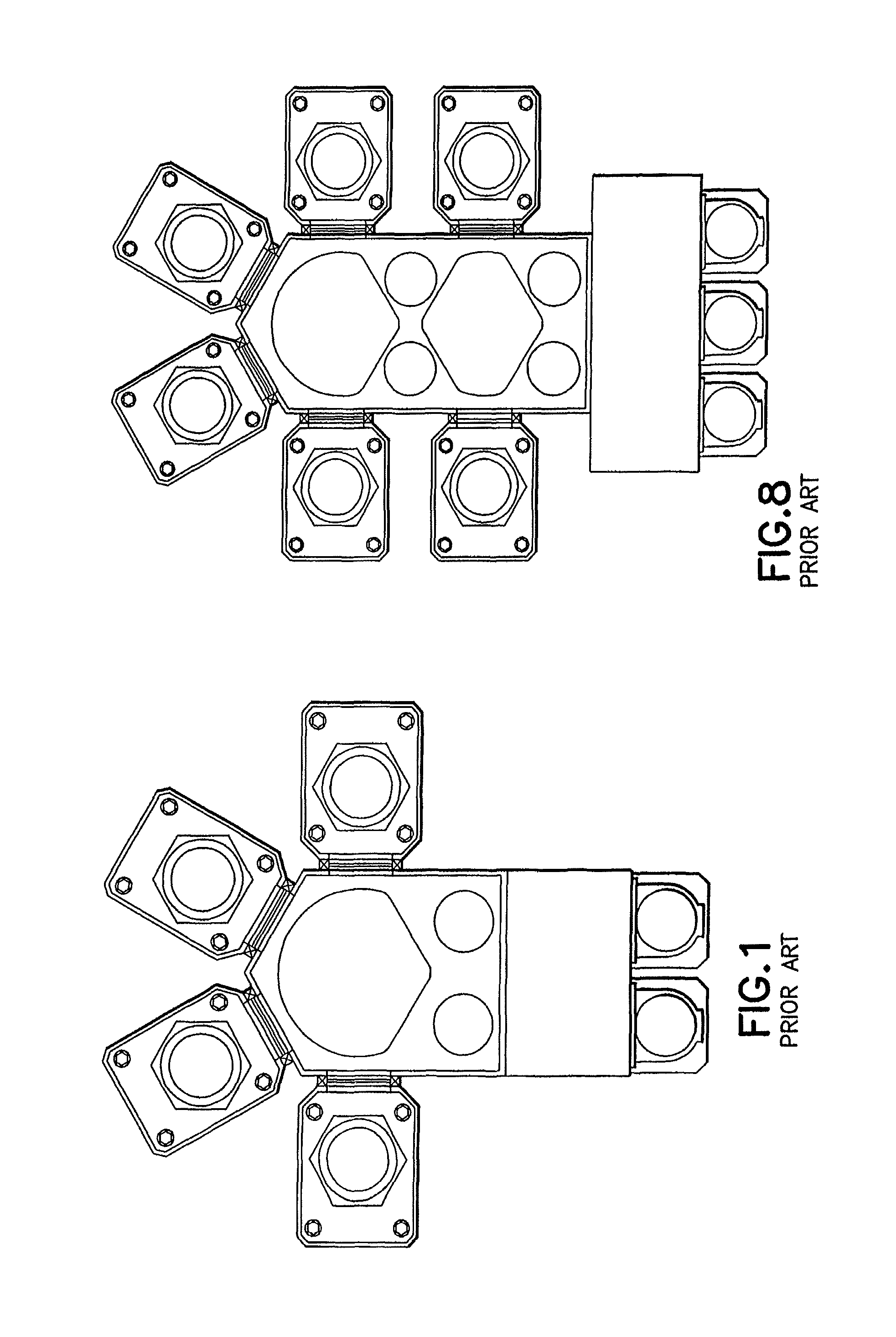
However, it appears that conventional processing apparatus have reached a dead end with respect to size reduction.
Moreover, conventional processing apparatus appear to have reached a limit with respect to increasing throughput per unit.
As can be realized from FIG. 1, throughput of the conventional processing apparatus is limited by the handling rate of the transport apparatus.

Method used


Image

  • Substrate processing apparatus
  • Substrate processing apparatus
  • Substrate processing apparatus

Examples


Embodiment Construction

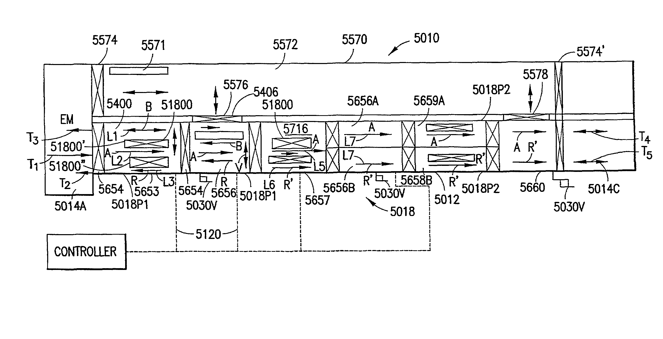
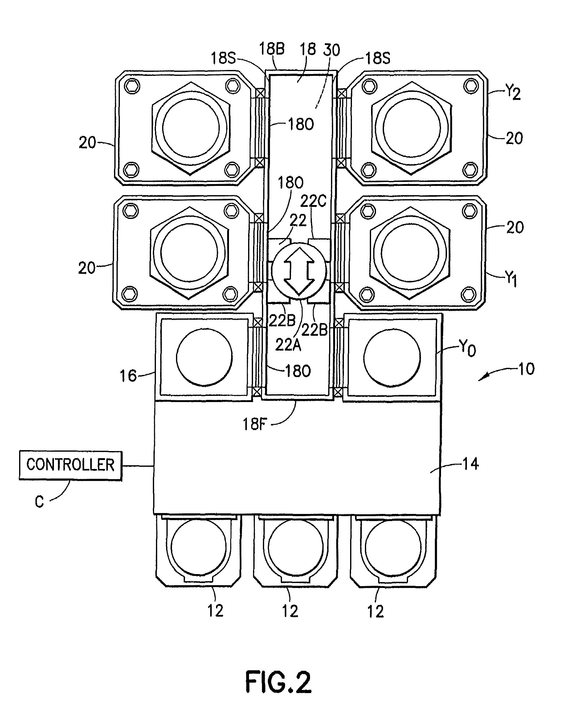
[0006]In accordance with one exemplary embodiment, a substrate processing apparatus is provided. The substrate processing apparatus comprising a transport chamber, a generally linear array of substrate holding modules alongside the transport chamber, and a substrate transport located in and movably mounted to the transport chamber. The transport chamber is capable of holding an isolated atmosphere isolated from an outside atmosphere. The chamber defines more than one substantially linear transport paths extending longitudinally along the transport chamber between opposing walls of the transport chamber. Each holding module of the linear array alongside the transport chamber is communicably connected to the chamber to allow passage of a substrate between transport chamber and holding module. The substrate transport located in the transport chamber is capable of transporting the substrate along the more than one substantially linear transport paths. The substrate transport has at leas...


PUM


Abstract

Substrate processing apparatus having a transport chamber, a linear array of substrate holding modules alongside the transport chamber, and a substrate transport located in the chamber. The chamber can hold an isolated atmosphere, and defines more than one substantially linear transport paths extending longitudinally along the transport chamber. The transport in the chamber is capable of transporting the substrate along the linear transport paths. The transport has a transporter capable of holding and moving the substrate. The transporter interfaces a wall of the transport chamber for moving along at least one of linear paths. The transport chamber has interfaces for mating with other substrate holding modules at opposite ends of the transport chamber. Each interface has an opening through which at least one of the more than one linear transport paths extends, and the transport chamber has a selectably variable longitudinal length between the interfaces.

Description

CROSS-REFERENCE TO RELATED APPLICATION(S)[0001]This is a continuation-in-part of application Ser. No. 10 / 962,787, filed Oct. 9, 2004, that is a continuation in part of application Ser. No. 10 / 624,987, filed Jul. 22, 2003, now U.S. Pat. No. 7,575,406 that claims the benefit of U.S. Provisional Application No. 60 / 397,895, filed Jul. 22, 2002, which is incorporated by reference herein in its entirety.BACKGROUND INFORMATION[0002]1. Field[0003]The embodiments and methods described herein relate to substrate processing apparatus and, more particularly, to substrate processing apparatus with chambers interconnected in a Cartesian arrangement.[0004]2. Brief Description of Earlier Developments[0005]One of the factors affecting consumer desire for new electronic devices naturally is the price of the device. Conversely, if the cost, and hence the price of new electronic devices can be lowered, it would appear that a beneficial effect would be achieved in consumer desires for new electronic dev...

Claims


Application Information

Patent Timeline
Patent Type & Authority Patents(United States)
IPC IPC(8): H01L21/677
CPCH01L21/67161H01L21/67173H01L21/67709H01L21/67724H01L21/67727H01L21/67742H01L21/67715Y10S414/139
Inventor HOFMEISTER, CHRISTOPHERCAVENEY, ROBERT T.
Owner BOOKS AUTOMATION US LLC
Learn More