
Methods and systems for dynamic scan compression

a dynamic scan and compression technology, applied in the field of scan compression, can solve the problems of more loss and smaller compressed data than smaller quantization values, and achieve the effect of preventing backtracking

Active Publication Date: 2011-06-07
LEXMARK INT INC +1
View PDF11 Cites 2 Cited by
  • Summary
  • Abstract
  • Description
  • Claims
  • Application Information

AI Technical Summary

Benefits of technology

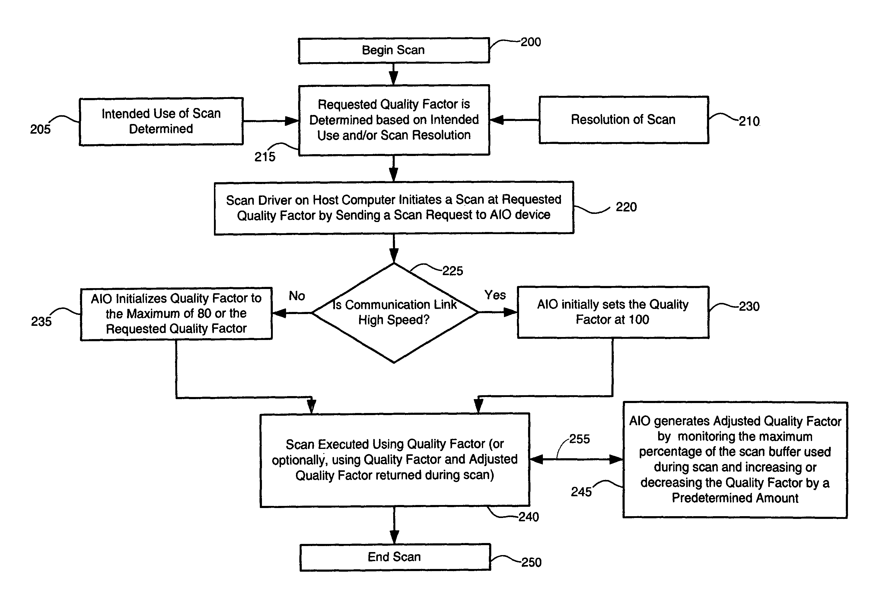
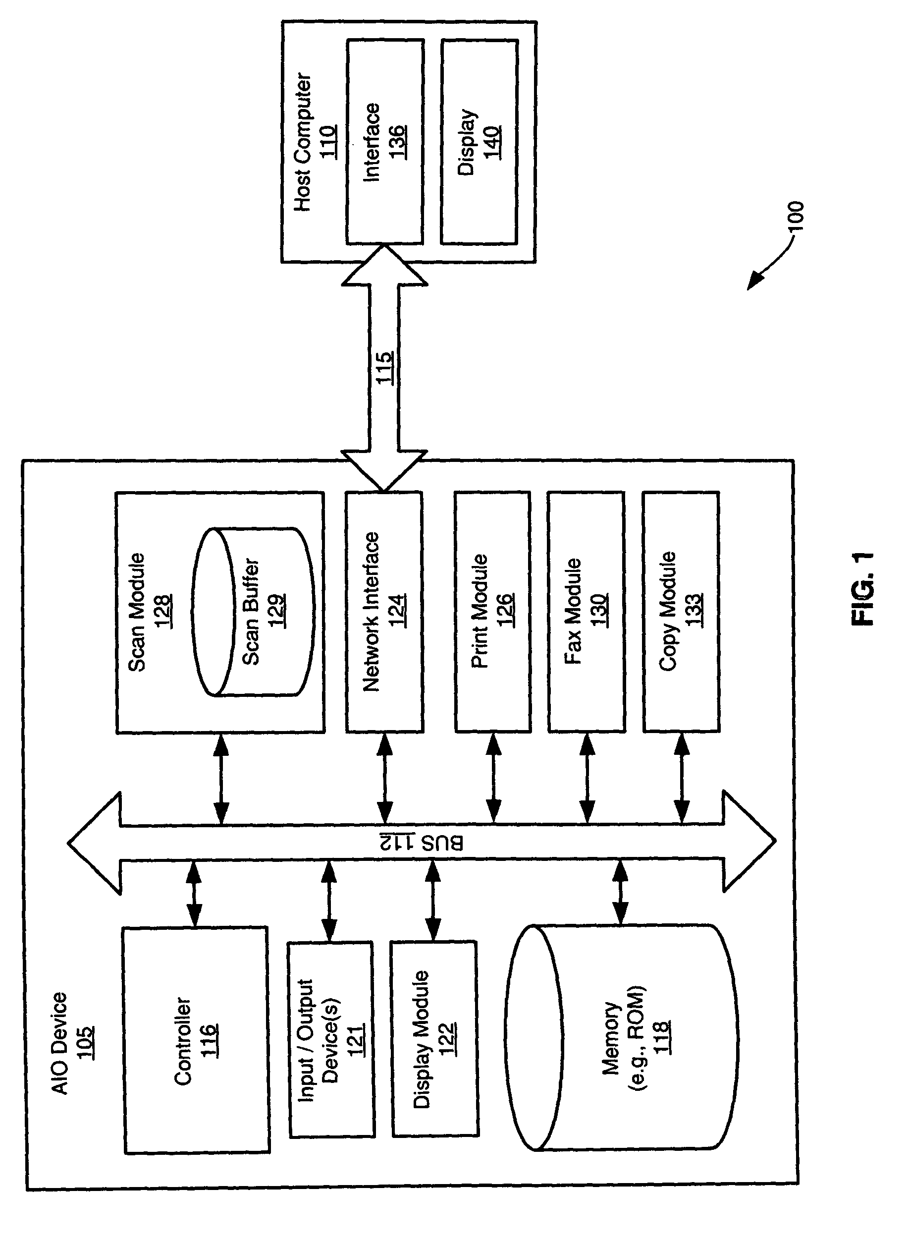
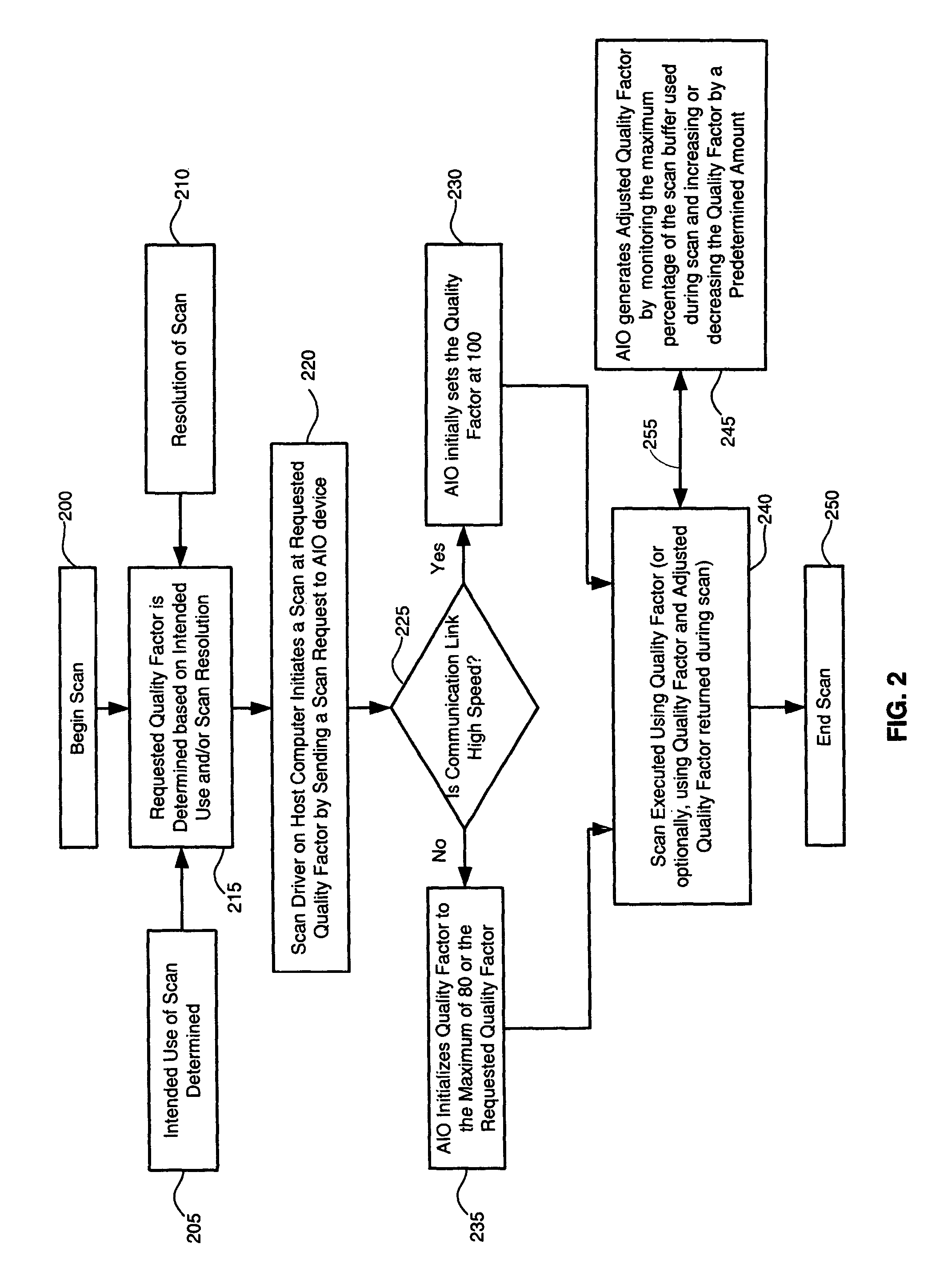
The present invention dynamically adjusts the quality factor for each scan based on the speed of communication used (e.g., high speed or full speed USB communication), and the amount of scan buffer available for scan data. Therefore, an AIO device or the like can monitor the data buffer (e.g., scan buffer) to determine the quality factor so that the AIO will not ‘backtrack’, as may otherwise occur when the scan buffer is full. In another embodiment, the AIO may use different types of compression to prevent backtracking. The present invention permits high-speed USB AIO devices to communicate via the USB 2.0 specification (supporting high-speed communication) with computers having high speed hosts and older computers having only full-speed hosts.

Problems solved by technology

Larger quantization values result in more loss and smaller compressed data than smaller quantization values.

Method used


Image

  • Methods and systems for dynamic scan compression
  • Methods and systems for dynamic scan compression
  • Methods and systems for dynamic scan compression

Examples


Embodiment Construction

The present invention will now be described more fully hereinafter with reference to the accompanying figures, in which like numerals indicate like elements throughout the several drawings. Some, but not all embodiments of the invention are described. Indeed, these inventions may be embodied in many different forms and should not be construed as limited to the embodiments set forth herein; rather, these embodiments are provided so that this disclosure will satisfy applicable legal requirements.

It should also be appreciated that the present invention is described below with reference to figures and flowchart illustrations of systems, methods, apparatuses and computer program products according to one or more embodiments of the invention. It will be understood that each block of the flowchart illustrations, and combinations of blocks in the flowchart illustrations, respectively, may be implemented by computer program instructions. These computer program instructions may be loaded onto...


PUM


Abstract

A method for compressing data includes transmitting a requested compression factor such as a quality factor known in JPEG compression, to a scanner or like peripheral device. The type of communication link between the scanner or like device and a host computer is identified, and based on the communication link type, the requested compression factor is altered to generate a new compression factor subsequently used to compress the data. The amount of buffer, such as scan buffer, used by the scanner or peripheral device may also be used to alter the compression factor prior to compression.

Description

CROSS REFERENCES TO RELATED APPLICATIONSNone.STATEMENT REGARDING FEDERALLY SPONSORED RESEARCH OR DEVELOPMENTNone.REFERENCE TO SEQUENTIAL LISTING, ETCNone.BACKGROUND1. Field of the InventionThe present invention is directed to scan compression, and more particularly, to methods and systems for dynamically altering data compression to reduce the amount of bandwidth required for transmission of data.2. Description of the Related ArtWhen scanning an image using a scanner or multi-functional device, such as an all-in-one (AIO) scanner / copier / printer / fax, scan data is transmitted to a host computer over a communication medium such as a USB. In conventional scanning systems, high resolutions scans may use all of the available bandwidth of a communication link between a scanner and a host. Even if a scanner can communicate scan data over the communication link at high speeds to preclude bandwidth issues, the receiving device, such as a computer, may be incapable of receiving scan data at su...

Claims


Application Information

Patent Timeline
Patent Type & Authority Patents(United States)
IPC IPC(8): G06K9/36G06F15/16G06K9/46
CPCH04N1/00795H04N19/164H04N1/00814H04N1/32363H04N1/32448H04N1/41H04N19/172H04N19/46H04N19/60H04N19/124H04N19/152H04N19/154H04N1/00811H04N2201/0094H04N2201/3298
Inventor BATES, JOHN BOOTHBROWN, BRIAN ANDREWRADEMACHER, TIMOTHY JOHN
Owner LEXMARK INT INC
Learn More