
Prosthesis fixation apparatus and methods

a technology of prosthesis and fixation apparatus, which is applied in the field of prosthesis fixation, can solve the problems of affecting the stability of the stent, and the weakened outward spring force of the self-expanded stent-graft, and the inability to prevent migration

Active Publication Date: 2011-06-07
MEDTRONIC VASCULAR INC
View PDF84 Cites 979 Cited by
  • Summary
  • Abstract
  • Description
  • Claims
  • Application Information

AI Technical Summary

Benefits of technology

This method effectively secures prostheses in challenging anatomical locations, reducing the risk of migration and leakage, and allows for precise placement without obstructing access to branch vessels, thereby ensuring the stability and effectiveness of the prosthesis placement.

Problems solved by technology

The abnormally dilated wall typically is weakened and susceptible to rupture.
For example, the outward spring force of a self-expanding stent-graft may not be sufficient to prevent migration.
This problem can be exacerbated when the vessel's fixation zone is not circumferential or it is calcified or when the proximal neck of an aneurysm, which extends toward the upstream branch vessel, is relatively short.
And when treating blood vessel aneurysms, for example, migration can result in leakage of blood around the prosthesis and into the aneurysmal sac, which, in turn, can cause rupture of the dilated vessel wall.
This problem is severe when the prosthesis is used to treat an aneurysm at or around the intersection of a major artery (e.g., the aorta) with the intersecting arteries (e.g., the renal, carotid or brachiocephalic arteries).

Method used


Image

  • Prosthesis fixation apparatus and methods
  • Prosthesis fixation apparatus and methods
  • Prosthesis fixation apparatus and methods

Examples


Embodiment Construction

[0033]The following description will be made with reference to the drawings where when referring to the various figures, it should be understood that like numerals or characters indicate like elements.

[0034]Generally speaking, the proximal end of the prosthesis and fastener generally are referred to as the ends closest to the heart during deployment. In contrast, the proximal end of the catheter or delivery device is the end nearest the operator, the distal end generally being that which is farthest from the operator. However, the stent graft and delivery system description may be consistent or opposite with this depending on the access location.

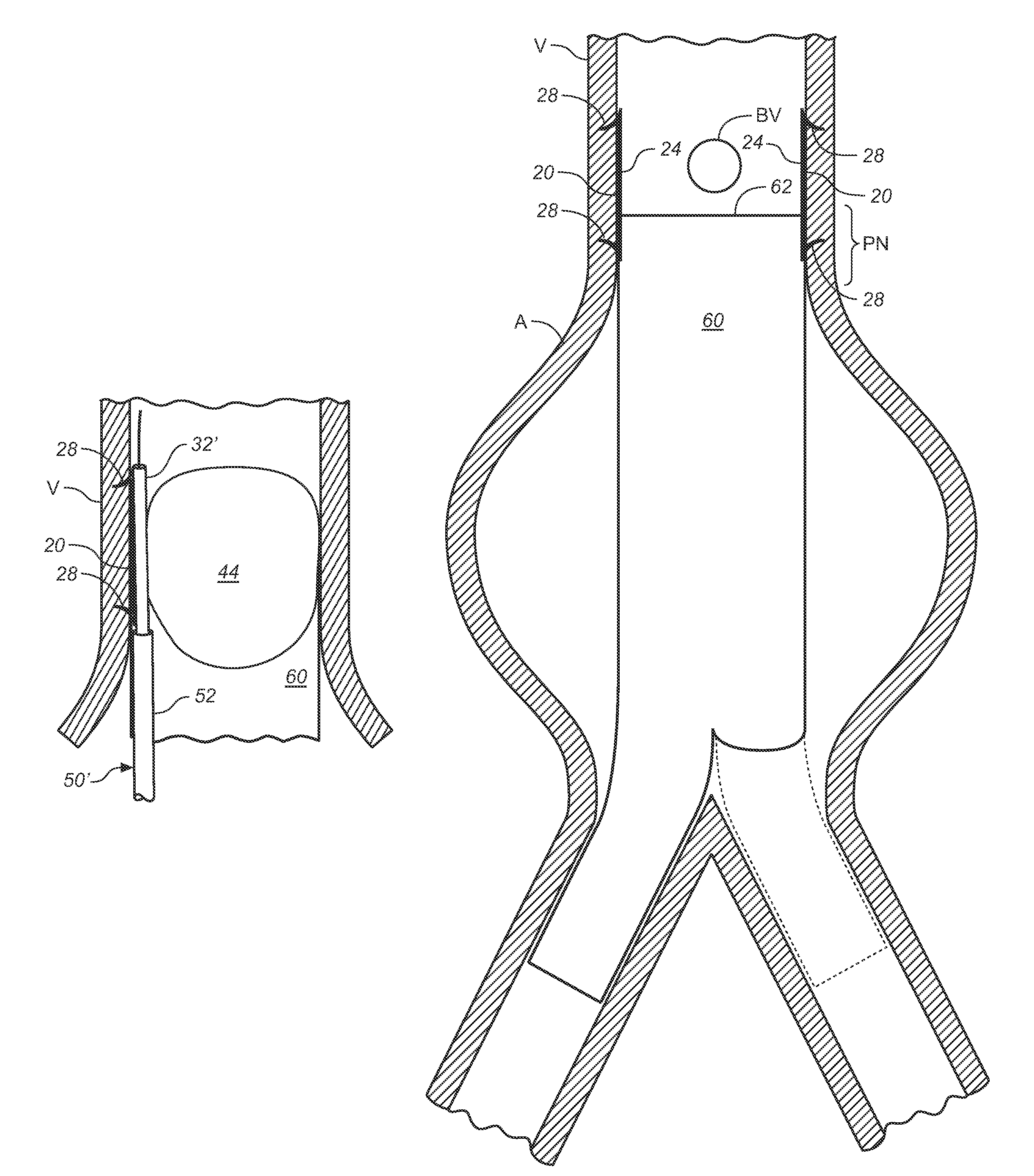
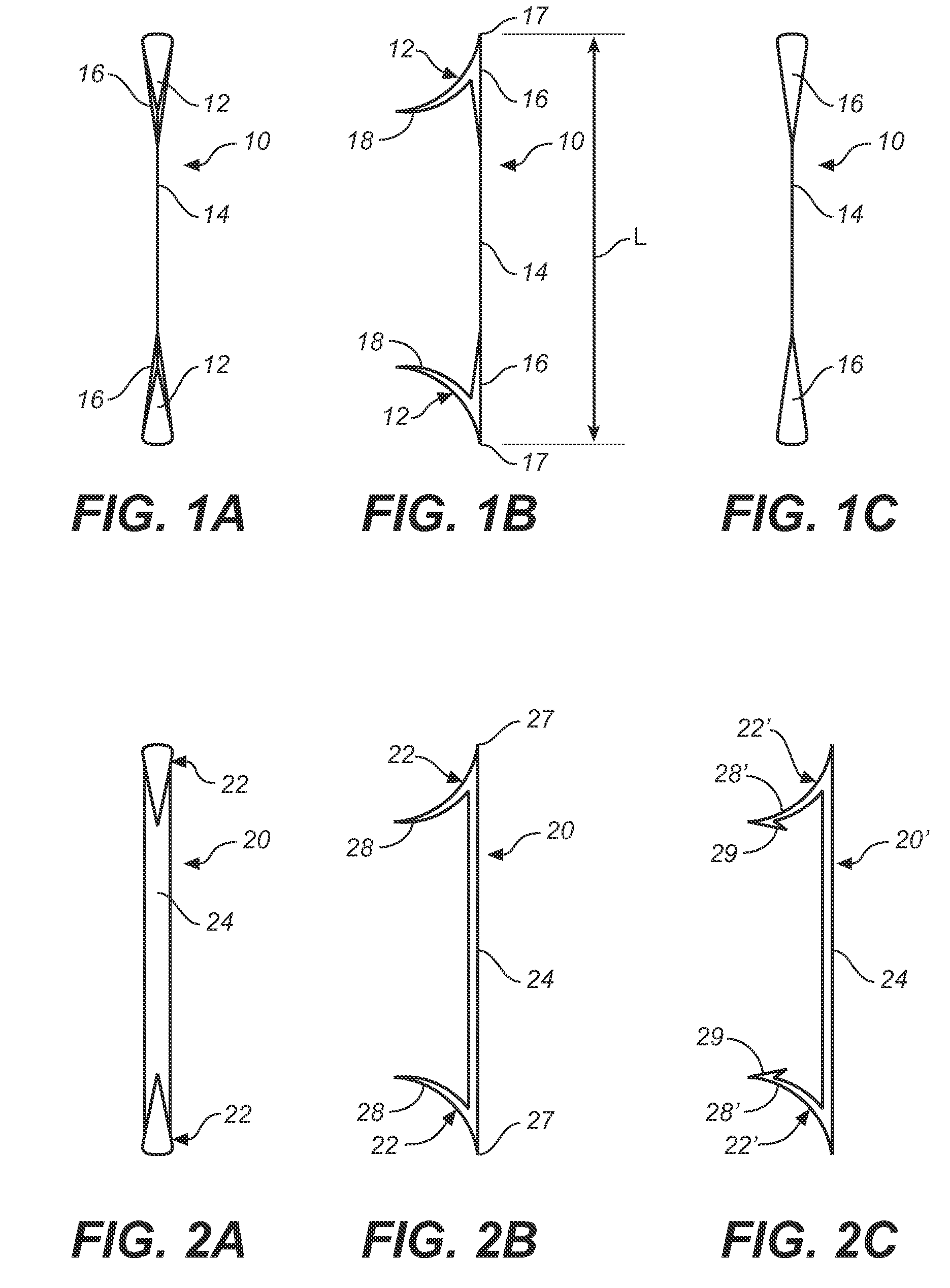
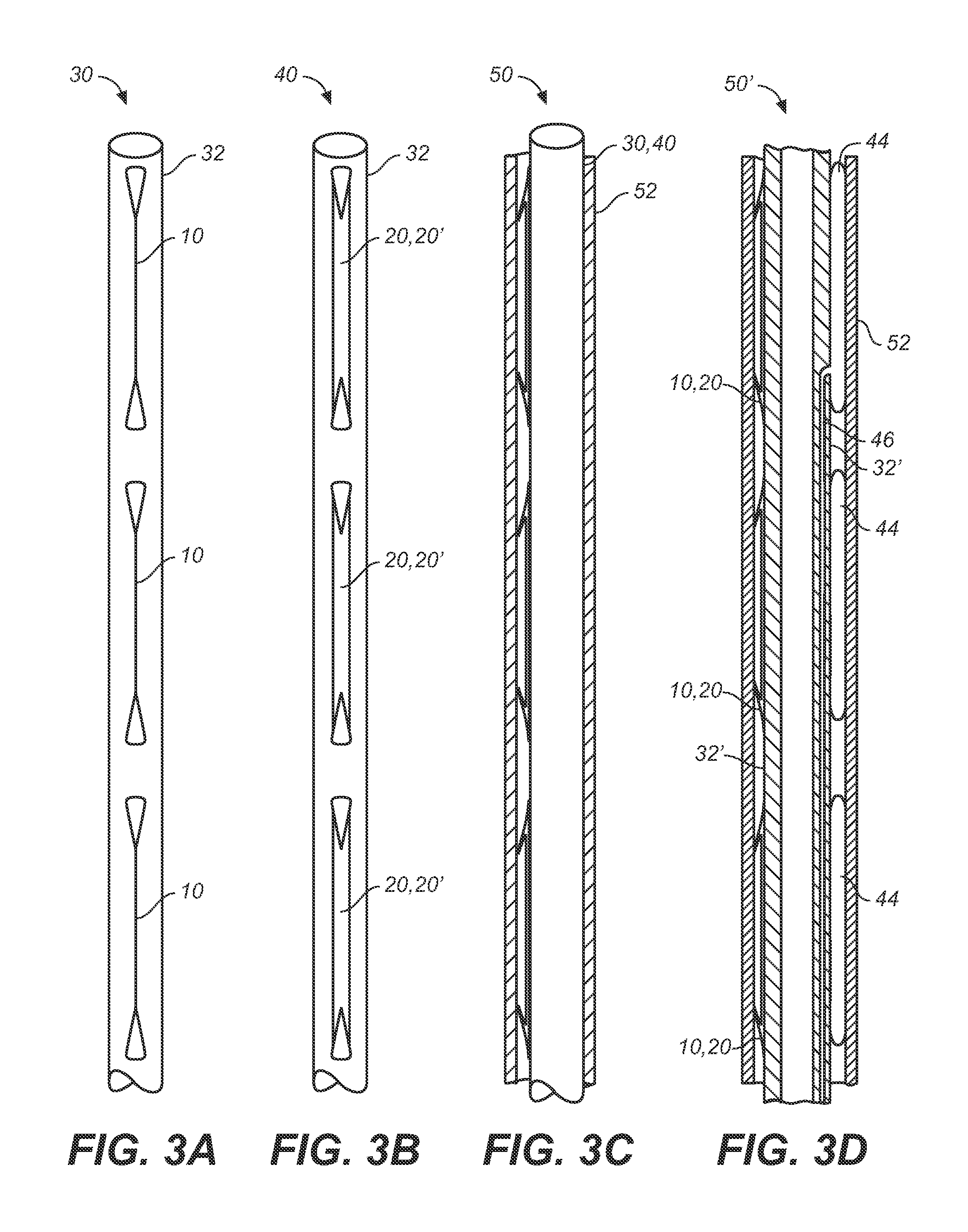
[0035]One embodiment generally involves apparatus and methods for prosthesis fixation, the apparatus comprises a surgical fastener having one end that passes through the prosthesis and into tissue that interfaces with an outer surface of the prosthesis and another end that is beyond the prosthesis and is secured to tissue without passing thr...


PUM


Abstract

A method of securing a prosthesis placed at a desired site in a passageway of a human body comprises delivering a fastener having a proximal piercing end portion and a distal piercing end portion to a site where a prosthesis having a tubular wall has been placed in the passageway, which has a wall, advancing the proximal piercing end portion beyond the prosthesis, penetrating the proximal piercing end portion into the wall of the passageway without passing the proximal piercing end portion through the tubular wall of the prosthesis, and passing the distal piercing end portion through the tubular wall of the prosthesis and into the wall of the passageway. One surgical fastener delivery apparatus for delivering a surgical fastener to a target site comprises a support having a first end, a second end, and a longitudinal axis and being adapted for placement in a passageway in a human body. A surgical fastener having a first piercing end portion, a second piercing end portion and a central portion extending therebetween and having a longitudinal axis is releasably mounted to the support with the central portion longitudinal axis generally parallel to the support longitudinal axis.

Description

FIELD OF THE INVENTION[0001]The invention relates to prosthesis fixation in a passageway in a human body such as an artery.BACKGROUND OF THE INVENTION[0002]Tubular prostheses such as stents, grafts, and stent-grafts (e.g., stents having an inner and / or outer covering comprising graft material and which may be referred to as covered stents) have been widely used in treating abnormalities in passageways in the human body. In vascular applications, these devices often are used to replace or bypass occluded, diseased or damaged blood vessels such as stenotic or aneurysmal vessels. For example, it is well known to use stent-grafts, which comprise biocompatible graft material (e.g., Dacron® or expanded polytetrafluoroethylene (ePTFE)) supported by a framework (e.g., one or more stent or stent-like structures), to treat or isolate aneurysms. The framework provides mechanical support and the graft material or liner provides a blood barrier.[0003]Aneurysms generally involve abnormal widening...

Claims


Application Information

Patent Timeline
Patent Type & Authority Patents(United States)
IPC IPC(8): A61F2/06
CPCA61B17/0401A61B17/064A61B17/068A61F2/848A61B2017/0427A61B2017/0464A61B2017/1157A61B2017/0412
Inventor CHU, JACKMORRIS, JONATHANMACHEK, JAMES
Owner MEDTRONIC VASCULAR INC
Learn More