
Enhanced communication via a serial interface

a serial interface and enhanced communication technology, applied in the field of enhanced communication via a serial interface, can solve the problems of requiring a bulky and expensive 2.5 mm or 3.5 mm universal headset jack (uhj)

Active Publication Date: 2011-05-24
NOKIA TECH OY
View PDF9 Cites 35 Cited by
  • Summary
  • Abstract
  • Description
  • Claims
  • Application Information

AI Technical Summary

Benefits of technology

[0019]Thus, the present invention allows to use the ID-pin of the first serial interface for data communication to a compatible second electronic device, which enables enhanced data communication between both devices, because besides the at least one data line of the serial interface connection a third line via the ID pin may be used for communication. For instance, any suited link system may be used for this communication, wherein the first electronic device may comprise a signal unit which is adapted to perform signaling according to the link system. For instance, said communication via the ID pin may be performed by a dual impedance Enhancement Control Interface (ECI), or by an accessory control interface (ACI).
[0021]Thus, the present invention may allow to use the full serial interface functionality via said at least one data line and may allow simultaneously a further communication via the ID pin without interfering the serial interface standard.
[0053]Thus, any loading interference between the D+ / D− lines and the audio lines may be eliminated.

Problems solved by technology

Small devices like mobile phones, audio players, personal digital assistants and so on can only provide limited space for connectors and interfaces for connection to other devices and accessories.
For instance, traditionally audio devices that used 2.5 mm or 3.5 mm universal headsets (UHS) required a bulky and expensive 2.5 mm or 3.5 mm universal headset jack (UHJ).

Method used


Image

  • Enhanced communication via a serial interface
  • Enhanced communication via a serial interface
  • Enhanced communication via a serial interface

Examples


Embodiment Construction

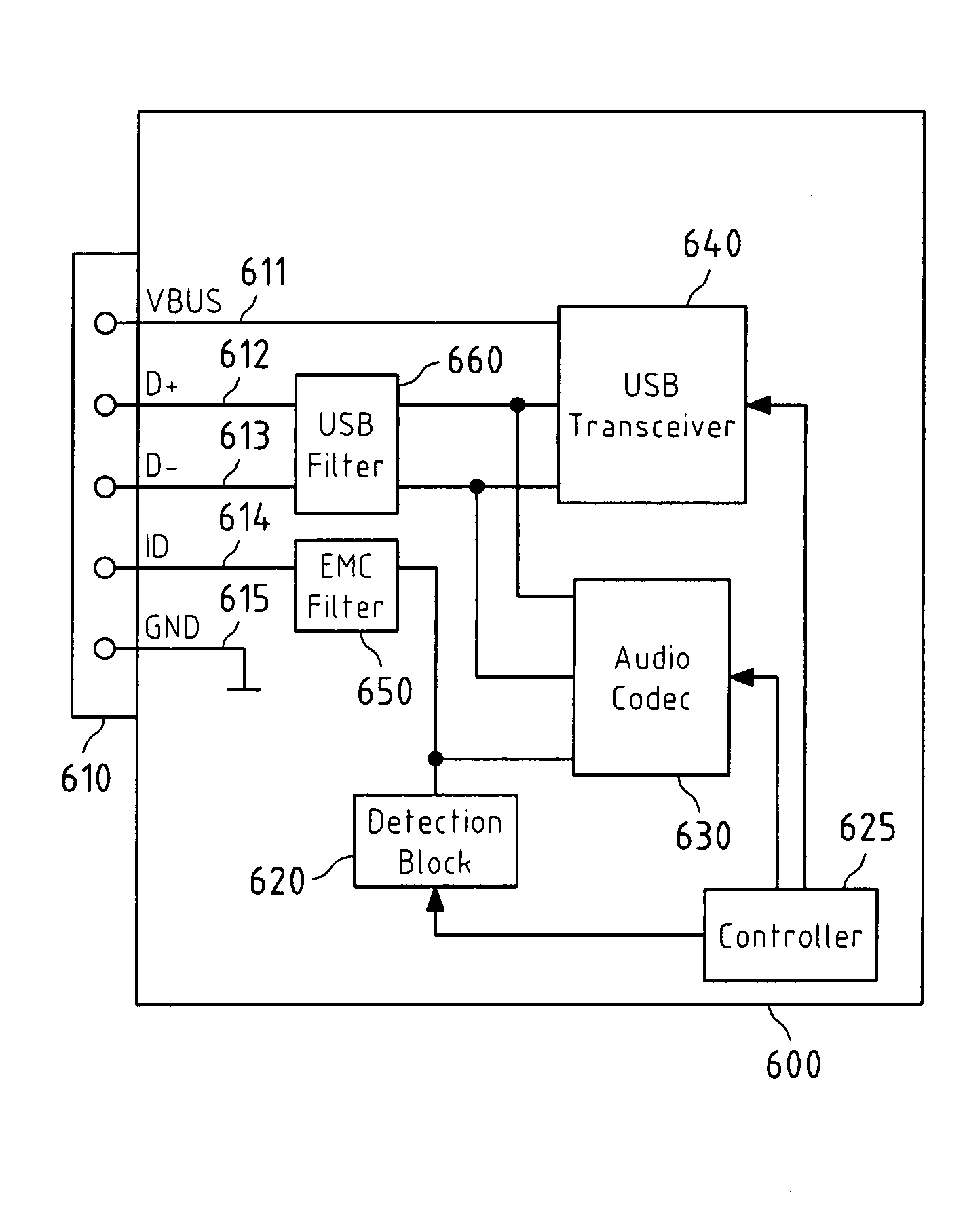
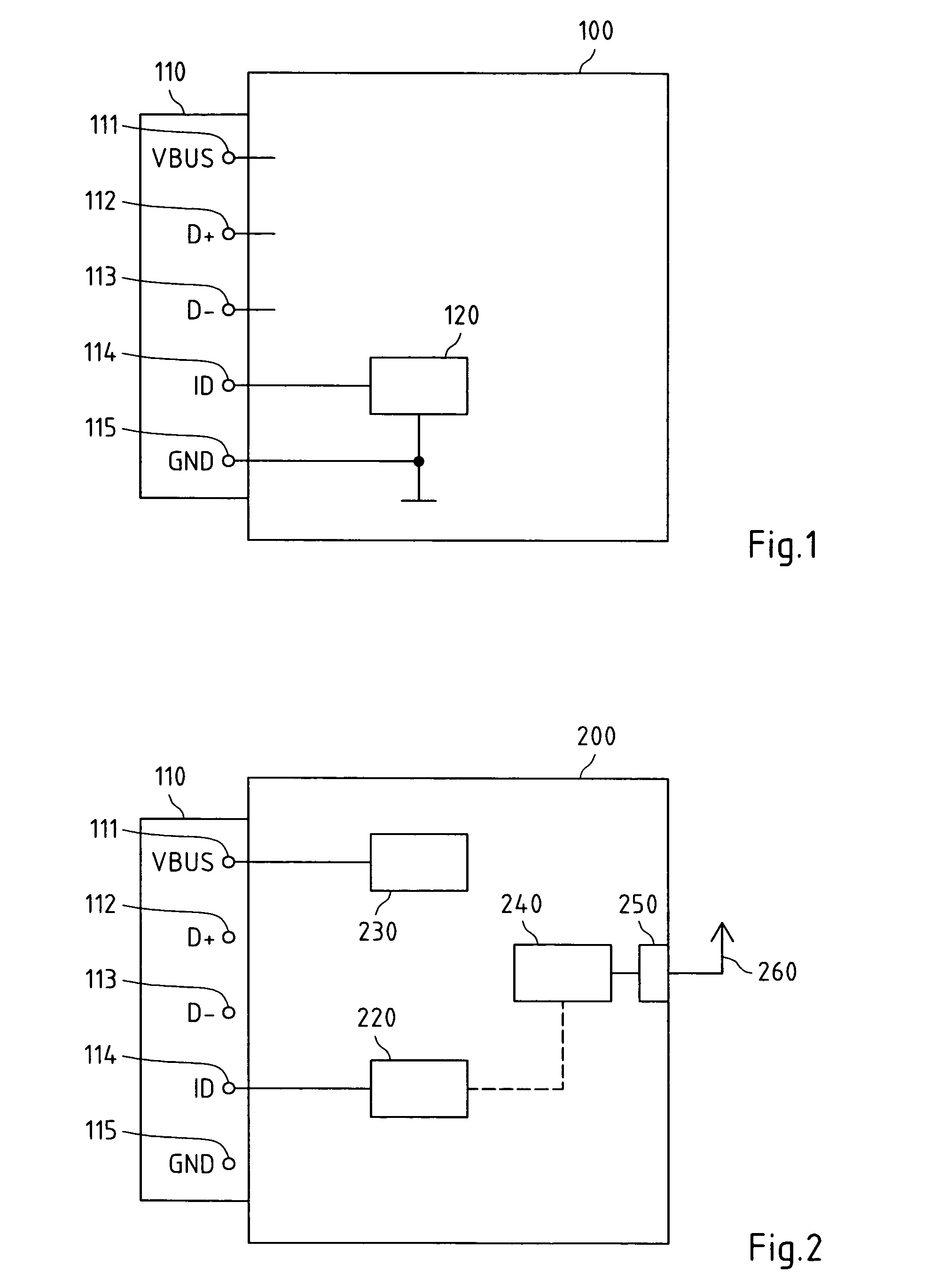
[0076]FIG. 1 depicts a block diagram of a first exemplary embodiment of a first electronic device 100 according to the present invention. The first device 100 comprises a serial interface 110, wherein said serial interface 110 comprises at least one data line 112, 113 and one identification pin 114. Furthermore, said serial interface may comprise a power supply line 111, and a ground line 115. The serial interface 110 of the first electronic 100 depicted in FIG. 1 is only an exemplary serial interface 100, e.g. said serial interface 100 may only comprise one data line or more than two data lines, and it is not restricted to an USB interface.

[0077]Thus, any kind of serial interfaces 110 comprising at least one data line and at least one ID line may be used for the serial interface 110 depicted FIG. 1. The same holds for the following exemplary embodiments.

[0078]The ID pin 114 of said serial interface is used to allow a communication with a compatible second electronic device (not sho...


PUM


Abstract

This invention relates to a method, a computer program product, an apparatus and a system enabling a communication between a first electronic device and a compatible second electronic device via the identification (ID) pin of a serial interface of the first electronic device.

Description

FIELD OF THE INVENTION[0001]This invention relates to a method, an apparatus, a computer program product and a system for an electronic device comprising a serial interface.BACKGROUND OF THE INVENTION[0002]A serial interface such as the Universal Serial Bus (USB) is a technology which provides a fast, cabled data connection between a complex device (e.g. a PC) which is called the Host and a connected peripheral (e.g. a mouse, keyboard etc.) which is called the Device.[0003]A serial interface according to the USB standard comprises two data lines (D+ and D−) a ground line (GND) and a voltage supply line (VBus).[0004]According to the USB standard, the D+ and D− lines are configured to be used for data transfer.[0005]The VBus line enables a connected device, which might not have an own power supply or where the device internal power supply is limited (e.g. a battery pack) to receive electrical power from the other connected device.[0006]In accordance with the USB standard the devices r...

Claims


Application Information

Patent Timeline
Patent Type & Authority Patents(United States)
IPC IPC(8): G06F3/00G06F13/00
CPCG06F13/4081G06F2213/0042
Inventor GALLANT, STEPHENREN, KENINGBARTSCHERER, MARKOINHA, KAI
Owner NOKIA TECH OY
Learn More