
Implantable microdevice with extended lead and remote electrode

a micro-device and remote electrode technology, applied in the field of implantable medical devices, can solve the problems of large system, large device size and complexity, and the nerve signal stimulation does not reach its natural destination, and achieve the effect of preventing the tethering of the muscle or nerve, and good anchoring characteristics

Inactive Publication Date: 2011-05-24
BOSTON SCI NEUROMODULATION CORP
View PDF64 Cites 597 Cited by
  • Summary
  • Abstract
  • Description
  • Claims
  • Application Information

AI Technical Summary

Benefits of technology

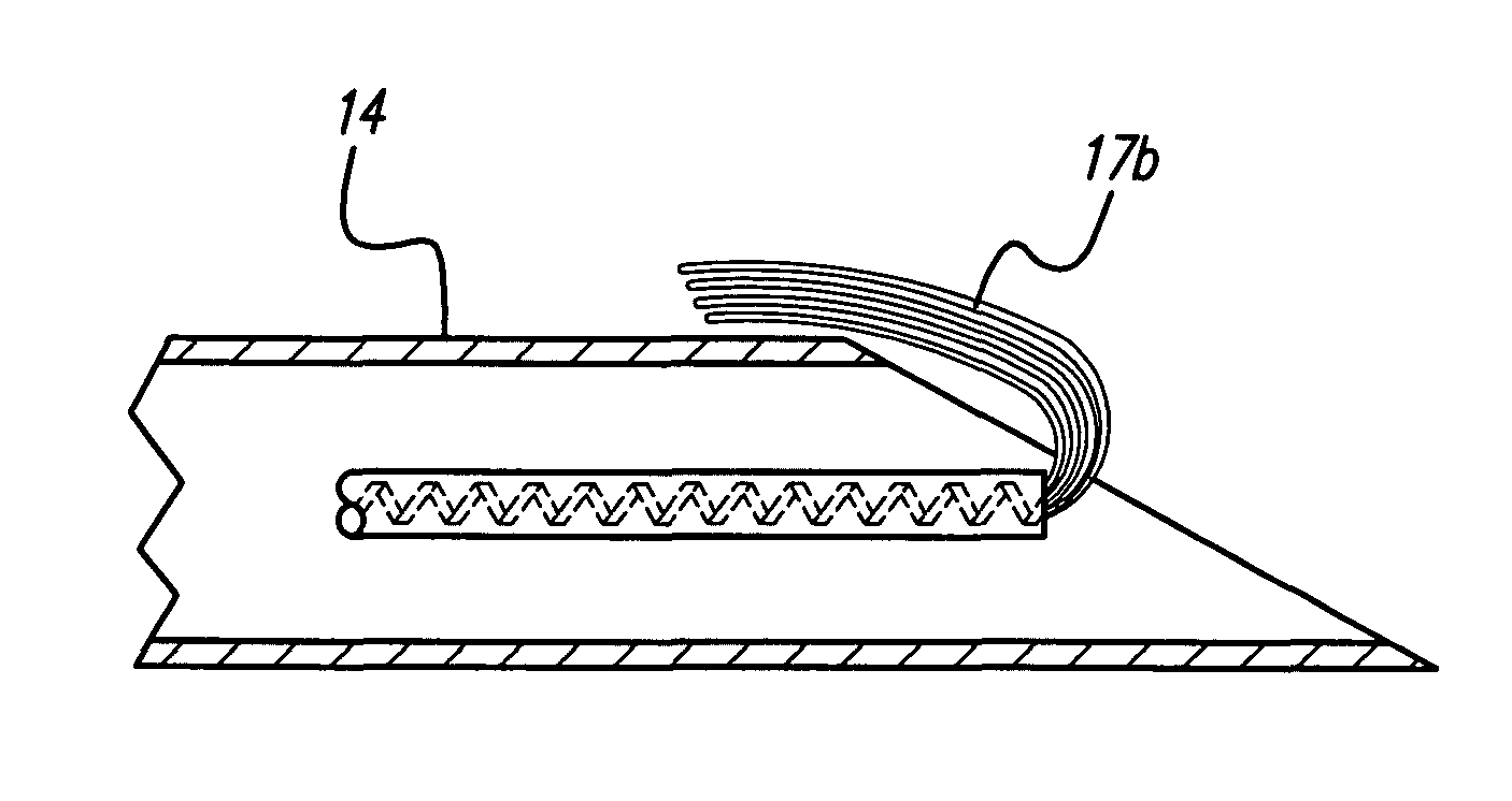
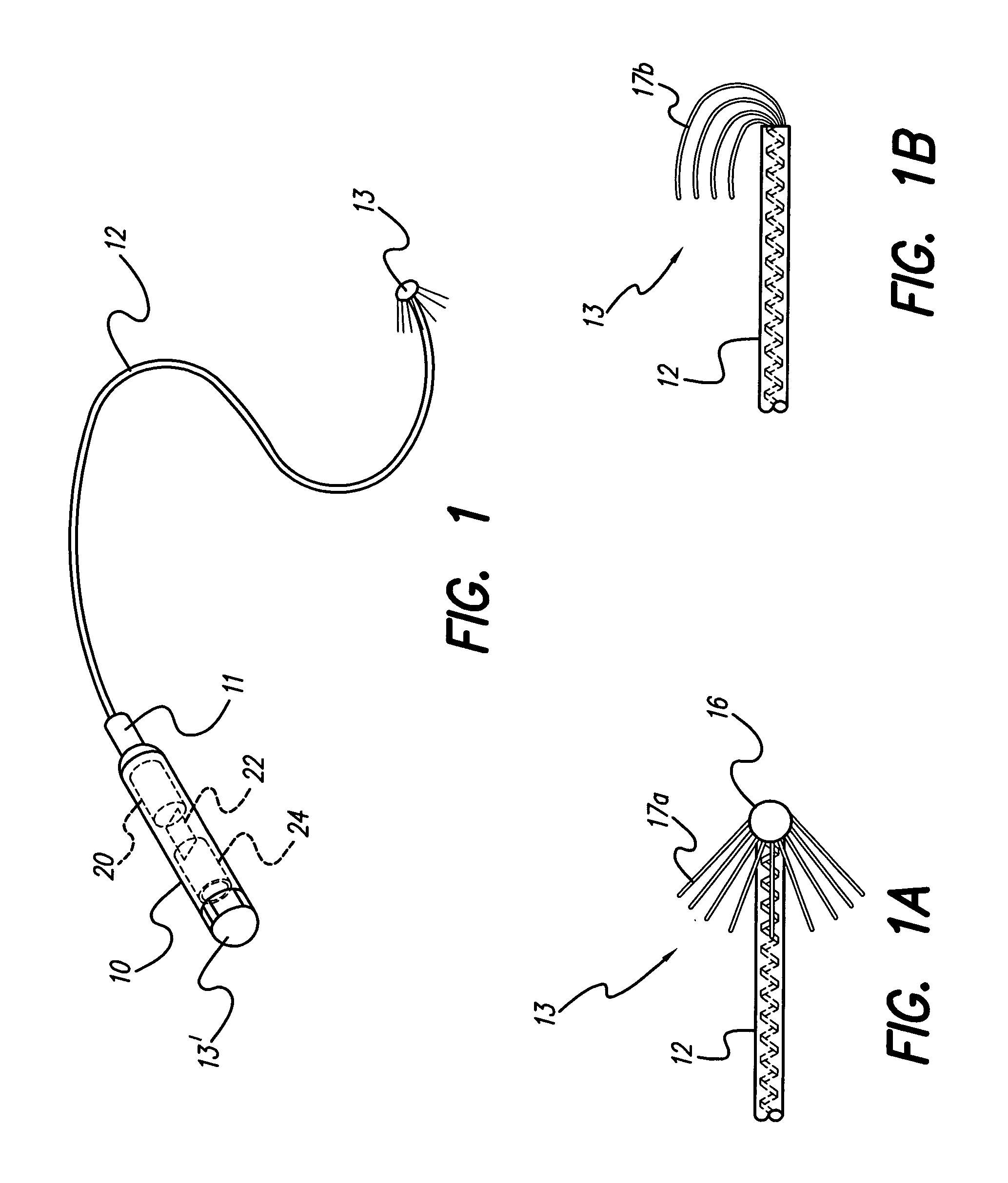
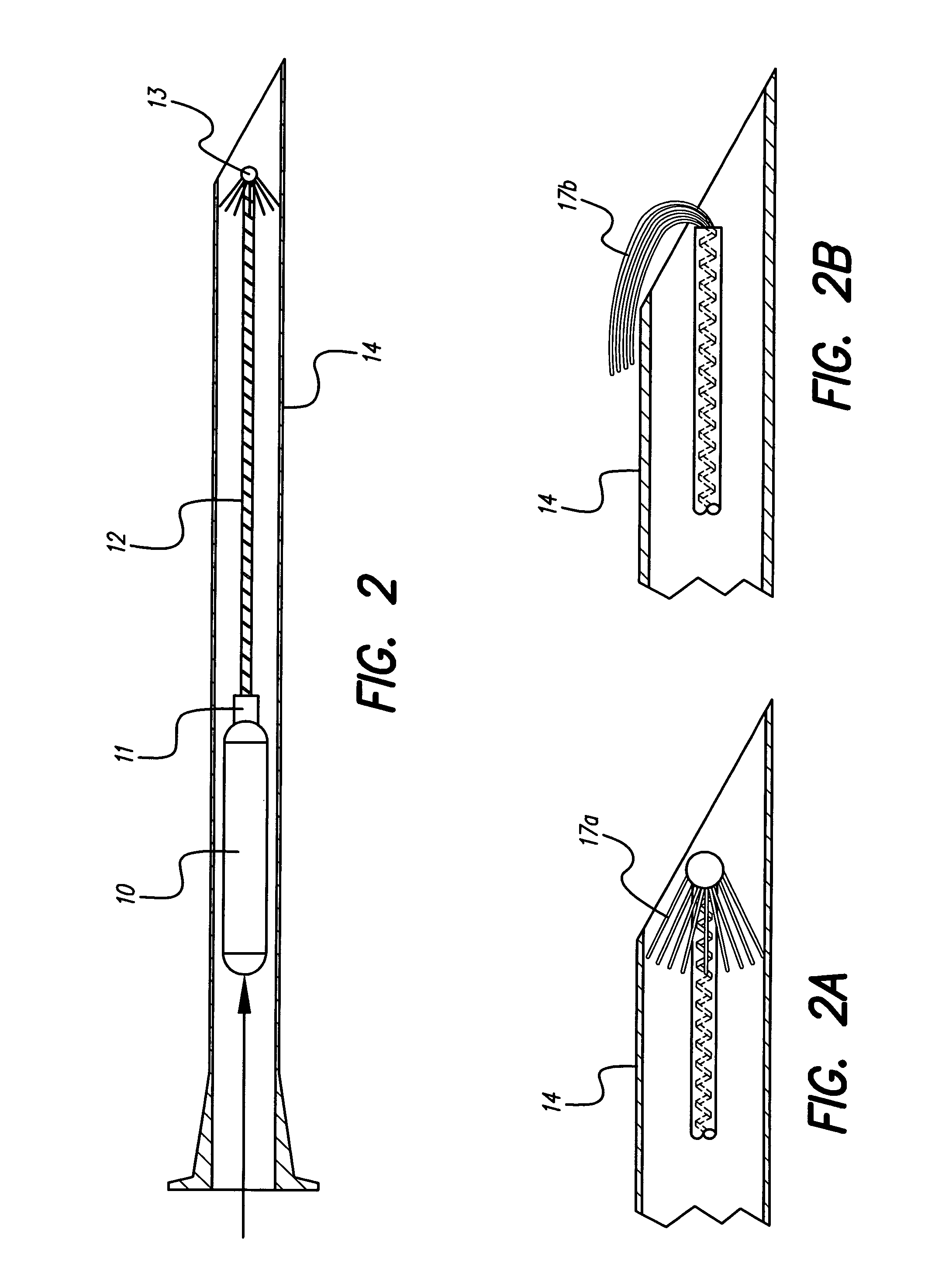
[0011]In accordance with another aspect of the invention, an implantable microdevice, e.g., a microstimulator or microsensor, is housed within a small, sealed, housing. When connected to an electrode, such housing includes all the requisite electronic circuitry for sensing a specified parameter, or generating electrical stimulation pulses that can be applied to a selected nerve or muscle, as well as circuitry for electromagnetically (i.e., inductively, optically, or through a radio frequency link) receiving power and control signals from an external source. The electrodes are remote from the housing and connected by a lead. Typically, the electrodes are configured for self attachment to a desired muscle or nerve, thereby permitting the microdevice to stimulate the muscle or nerve, and / or to sense a given parameter at or near the muscle or nerve. Any type of electrode attachment scheme known in the art, or yet to be developed, may be used to attach the electrode to the muscle or nerve, such as using helical, deep brain, chip, or cuff electrodes. The use of an electrode with exposed wire strands folding back on an electrode lead is preferred because such an electrode has good anchoring characteristics. Advantageously, the electrodes are sufficiently small to allow attachment to a single muscle or nerve, thereby preventing tethering of the muscle or nerve.

Problems solved by technology

Local nerves and muscles may function, but, for various reasons, injury, stroke, or other cause, the stimulating nerve signals do not reach their natural destination.
Such devices vary in size and complexity.
For example, some systems comprise large, bulky systems feeding electrical pulses by conductors passing through the skin.
However, complications, including the possibility of infection, arise in the use of muscle, nerve or other stimulators which have conductors extending through the skin or which have nerve-stimulating electrodes that puncture or penetrate the epineurium.
However, in the use of implanted stimulators, difficulties arise in providing suitable, operable stimulators which are small in size and have the capability to receive and store sufficient energy and control information to satisfactorily operate them without direct connection.
Unfortunately, the muscle or nerve that requires stimulation or sensing is often deep inside the body and very inefficient inductive power transmission results.
However this approach is technically difficult and would create a requirement for extensive surgery if it is necessary to remove the system in case of failure or at the end of the battery life.
In some body locations where an extreme degree of flexing takes place (for example the ankle, knee, or elbow), it would be difficult to easily attach the external coil.

Method used


Image

  • Implantable microdevice with extended lead and remote electrode
  • Implantable microdevice with extended lead and remote electrode
  • Implantable microdevice with extended lead and remote electrode

Examples


Embodiment Construction

[0028]The following description is of the best mode presently contemplated for carrying out the invention. This description is not to be taken in a limiting sense, but is made merely for the purpose of describing the general principles of the invention. The scope of the invention should be determined with reference to the claims.

[0029]As seen in FIG. 1, the present invention relates to a microdevice 10 that uses an electrode 13 connected at a distal end of a flexible electrode lead 12. A proximal end of the flexible electrode lead 12 is removably connected to a connector 11 on a microdevice 10 and thereby electrically connected to an electronic circuit within the microdevice 10. The electrode 13 may be located in a desired implant location, e.g., deep within body tissue near or at a desired nerve bundle or muscle tissue. The microdevice 10 may be located near the surface of the skin to facilitate electromagnetic power transmission and control. In one embodiment, the microdevice 10 c...


PUM


Abstract

An implantable microdevice includes at least one electrode detachably connected to electronic circuitry housed in an hermetically-sealed micro housing. The micro housing has a length no more than about 10 mm. In one embodiment, the electrode is located at a distal end of an electrode lead, and a proximal end of the electrode lead is removably inserted into a connector that forms part of the micro housing.

Description

[0001]This application is a Divisional of U.S. patent application Ser. No. 10 / 188,465, filed Jul. 2, 2002 now abandoned, which application is a Divisional of U.S. patent application Ser. No. 09 / 624,130, filed Jul. 24, 2000, now abandoned, which application in turn claims the benefit of U.S. Provisional Patent Application Ser. No. 60 / 156,980, filed Oct. 1, 1999, which applications are all incorporated herein by reference in their entirety.BACKGROUND OF THE INVENTION[0002]The present invention relates to implantable medical devices, and more particularly to an implantable microminiature stimulator (or “microstimulator”) or microminiature sensor (or “microsensor”) comprising a microdevice and one or more remote electrodes adapted to attach to one or more muscle or nerve fibers (or muscles or nerves) and to electrically stimulate the muscle or nerve at the point of attachment in a controlled manner, or to sense one or more specific parameters that originate at or near the point of attac...

Claims


Application Information

Patent Timeline
IPC IPC(8): A61N1/05A61N1/08A61N1/372
CPCA61N1/0551A61N1/37205A61N1/0558
Inventor KUZMA, JANUSZ A
Owner BOSTON SCI NEUROMODULATION CORP
Learn More