Eureka AIR delivers breakthrough ideas for toughest innovation challenges, trusted by R&D personnel around the world.

Motorcycle and muffler structure

a technology for mufflers and motorcycles, which is applied in the direction of machines/engines, cycle equipment, instruments, etc., can solve the problem of heat of the muffler not being smoothly released to the outside of the muffler cover

Inactive Publication Date: 2011-05-24
YAMAHA MOTOR CO LTD
View PDF12 Cites 28 Cited by
  • Summary
  • Abstract
  • Description
  • Claims
  • Application Information

AI Technical Summary

Benefits of technology

[0009]The preferred embodiments of the present invention have been developed in view of the above-mentioned and / or other problems in the related art. The preferred embodiments of the present invention can significantly improve upon existing methods and / or apparatuses.
[0010]Among other potential advantages, some preferred embodiments of the present invention can provide a motorcycle capable of smoothly releasing heat of a muffler to an outside of a muffler cover.
[0012]In accordance with this motorcycle, the central axis of the muffler cover is offset from the central axis of the muffler in the radial direction. This facilitates obtainment of the gap between the muffler and the muffler cover, thereby improving heat dissipation of the muffler. The muffler cover and the end cap are separately formed, and thus heat dissipation of the muffler can be further improved.

Problems solved by technology

However, there is a problem with the conventional structure of the aforementioned muffler cover that the muffler cover and the rear cover are integrally formed and thus heat of the muffler is not smoothly released to the outside of the muffler cover.

Method used


Image

  • Motorcycle and muffler structure
  • Motorcycle and muffler structure
  • Motorcycle and muffler structure

Examples


Embodiment Construction

[0026]In the following paragraphs, some preferred embodiments of the invention will be described by way of example and not limitation. It should be understood based on this disclosure that various other modifications can be made by those in the art based on these illustrated embodiments.

[0027]Hereinafter, an embodiment of the present invention will be described with reference to the attached drawings.

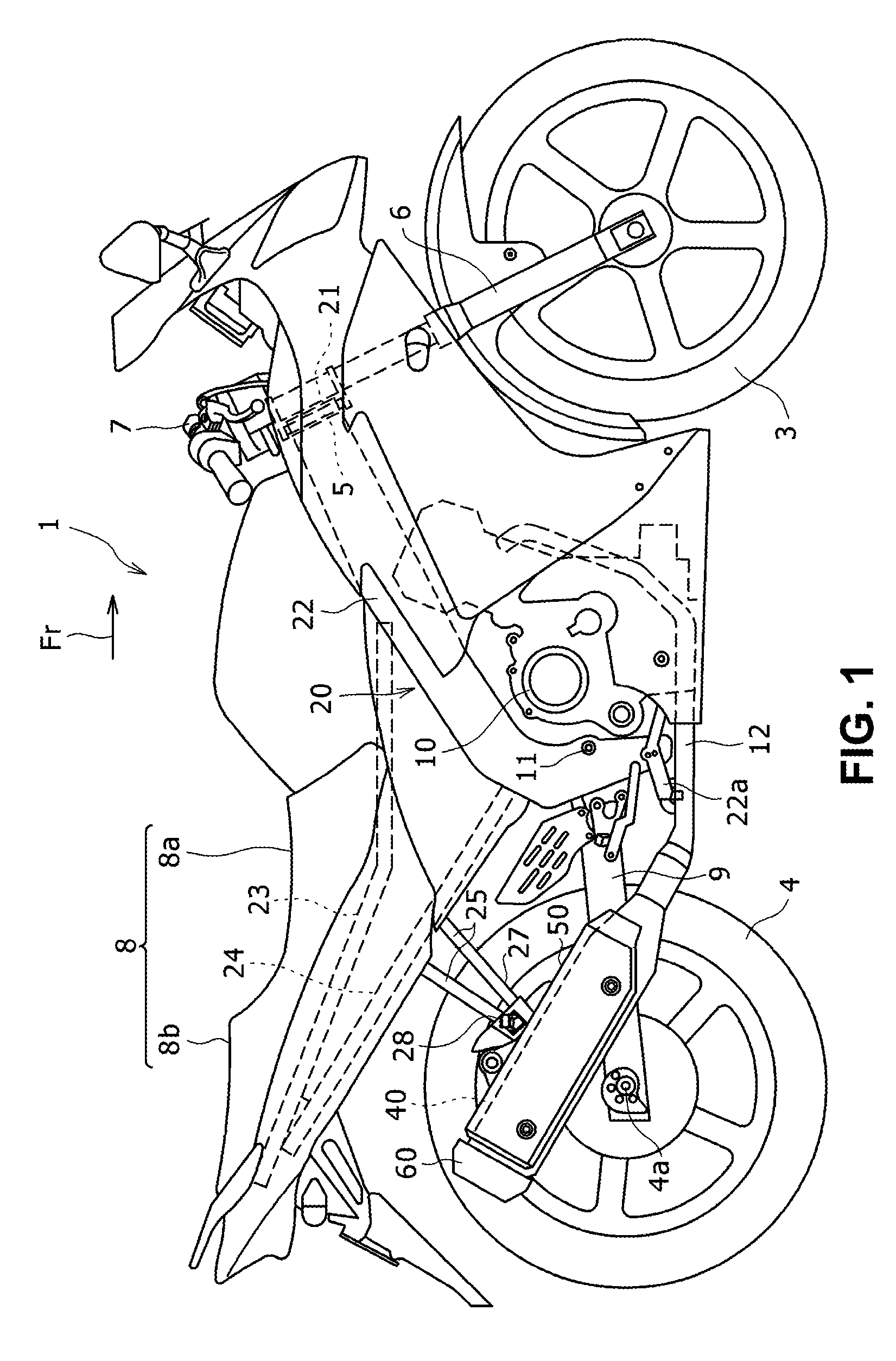
[0028]FIG. 1 is a side view of a motorcycle 1 according to an embodiment of the present invention. FIG. 2 is a side view of a muffler 40 mounted on the motorcycle 1 and the vicinity thereof. FIG. 3 is an exploded perspective view of the muffler 40, a muffler cover 50, and an end cap 60.

[0029]As shown in FIG. 1, the motorcycle 1 includes, in addition to the muffler 40, the muffler cover 50 and the end cap 60, a front wheel 3, a rear wheel 4, an engine 10, and a vehicle body frame 20. The vehicle body frame 20 includes a head pipe 21, a main frame 22, and seat rails 23, and back stays 24....


PUM


Abstract

A motorcycle has a muffler 40, a muffler cover 50 for covering a part of a side surface (outer peripheral surface) of the muffler 40 and an end cap 60 for covering the muffler 40 from a rear side thereof. The end cap 60 is separately formed from the muffler cover 50 and disposed away from the muffler cover 50. The muffler cover 50 is mounted on the muffler 40 in a manner such that a central axis of the muffler cover 50 is offset from a central axis of the muffler 40 in a radial direction.

Description

[0001]This application claims priority under 35 U.S.C. §119 to Japanese Patent Application No. 2007-284231 filed on Oct. 31, 2007, the entire disclosure of which is incorporated herein by reference in its entirety.BACKGROUND OF THE INVENTION[0002]1. Field of the Invention[0003]The preferred embodiments of the present invention relate, inter alia, to a motorcycle equipped with a muffler cover, and a muffler structure having a muffler cover for covering a muffler disposed on a side of a rear wheel of a motorcycle.[0004]2. Description of the Related Art[0005]The following description sets forth the inventors' knowledge of related art and problems therein and should not be construed as an admission of knowledge in the prior art.[0006]In motorcycles, a muffler is generally disposed on a side of a rear wheel for, e.g., reducing exhaust sound. In some motorcycles, a side surface of the muffler is partially covered by a muffler cover of an arc-shape in cross section. Japanese Unexamined Lai...

Claims


Application Information

Patent Timeline
Patent Type & Authority Patents(United States)
IPC IPC(8): F01N13/00F02B77/11F01N13/14B62J23/00B62M7/02F01N13/08F01N13/20
CPCF01N13/14F01N13/20F01N2590/04F01N2260/20
Inventor YAMAMOTO, MASANORIMATSUURA, SHIGEYUKI
Owner YAMAHA MOTOR CO LTD
Why Eureka
Eureka Blog
Learn More