
Storage array partitioning

a technology of storage arrays and partitions, applied in computing, instruments, electric digital data processing, etc., can solve problems such as adding to overhead, and achieve the effects of reducing the number of non-native global memory accesses, improving failure isolation, and little or no impa

Active Publication Date: 2011-05-17
EMC IP HLDG CO LLC
View PDF6 Cites 11 Cited by
  • Summary
  • Abstract
  • Description
  • Claims
  • Application Information

AI Technical Summary

Benefits of technology

[0025]The advantages of the system described herein include improved failure isolation as well as providing a mechanism for parallel independent upgrades and independent testing. The system is designed so that modification to one of the partitioned storage subsystems has little or no impact on other partitioned storage subsystems. In addition, the different partitioned storage subsystems may communicate with each other without the need for additional cabling and / or other interconnection provisions (e.g., a SAN) but still may be managed using a single management console (or similar) coupled to the storage array.
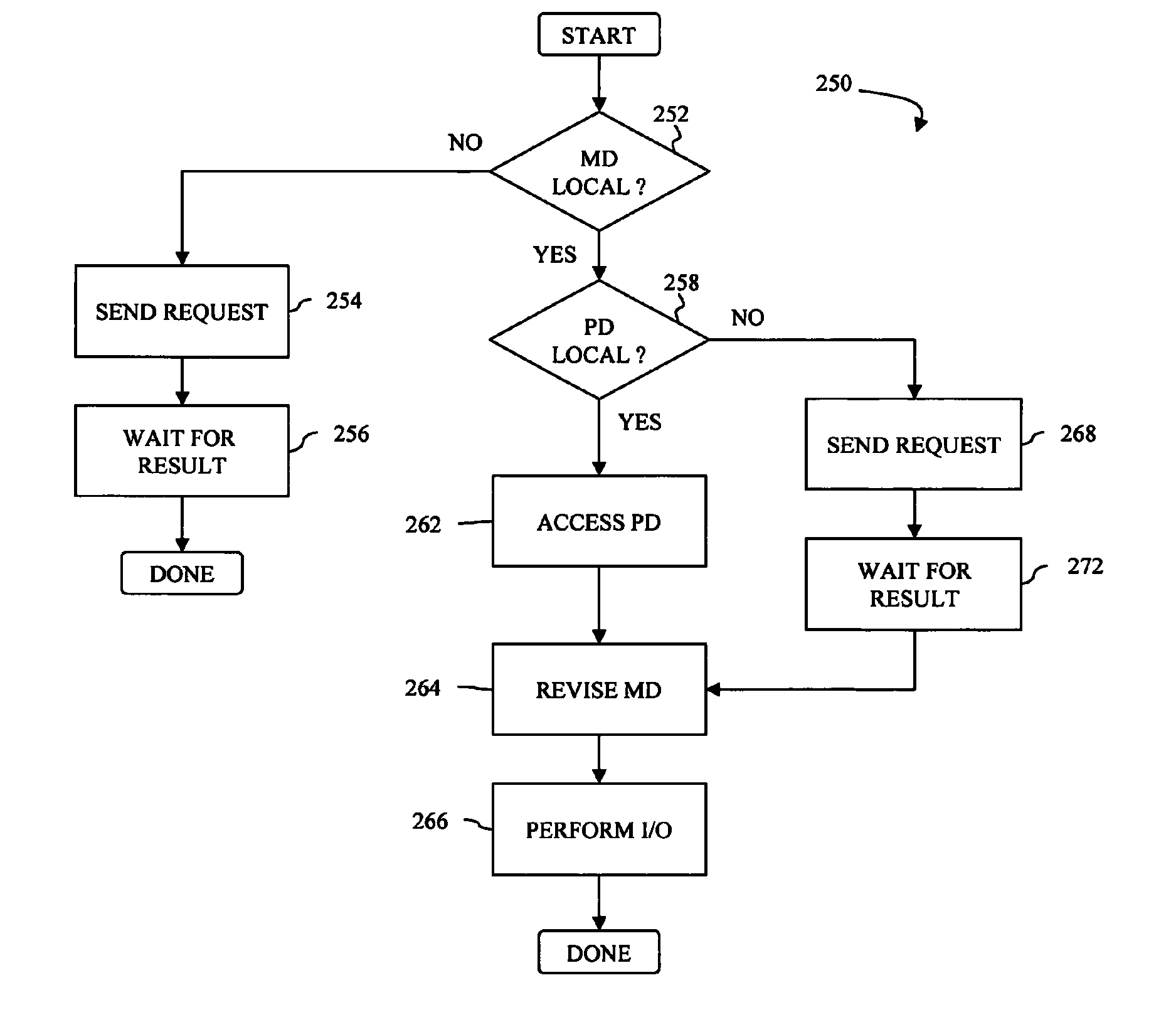
[0026]Transferring I / O operations to a director having a portion of the global memory that contains corresponding metadata reduces the number of non-native global memory accesses and thus is more efficient. Transferring I / O operations among directors may also improve board utilization and port utilization (connectivity to a single port) and may eliminate constraints on the number of logical devices that may use a single port.
[0027]Distributing logical devices among directors in a partitioned storage subsystem such that each director is a primary director for approximately the same number of logical devices (or approximately the same I / O access load) provides better utilization of the directors.

Problems solved by technology

Such an arrangement may be inefficient in some cases and may even require active allocation of resources, which adds to overhead.

Method used


Image

  • Storage array partitioning
  • Storage array partitioning
  • Storage array partitioning

Examples


Embodiment Construction

[0043]Referring to FIG. 3, a diagram shows a storage array 100 that includes a plurality of director boards 101-109 that perform functions like the directors 42a-42c, described above. In some embodiments, one or more of the director boards 101-109 may have multiple independent processor systems thereon and may be able to provide an emulation instance for more than one independent director, including simultaneously providing emulation instances for at least two different types of directors (e.g., an HA and a DA) on a single one of the director boards 101-109. In an embodiment herein, the director boards 101-109 each have eight independent processor systems, but more or less processor systems are also possible.

[0044]Accordingly, each director board may contain a plurality of director emulation instances running thereon although many of the features described herein work in cases where each of the director boards 101-109 has a single director emulation instance. Thus, for the discussio...


PUM


Abstract

A storage array includes a plurality of directors, each having at least one processor thereon and a global memory distributed among the plurality of directors. A different portion of the global memory is provided on each of the directors. A interconnect fabric is coupled to each of the directors. Global memory accesses performed by one director to access memory of another director through the interconnect fabric. The storage array also includes a plurality of partitioned storage subsystems, each including a separate subset of the directors, where each of the partitioned storage subsystems handles I / O operations for a plurality of logical devices independently of I / O operations for logical devices of other ones of the partitioned storage subsystems, the I / O operations using metadata provided in the global memory of the corresponding directors and containing information that correlates logical device data with physical device data.

Description

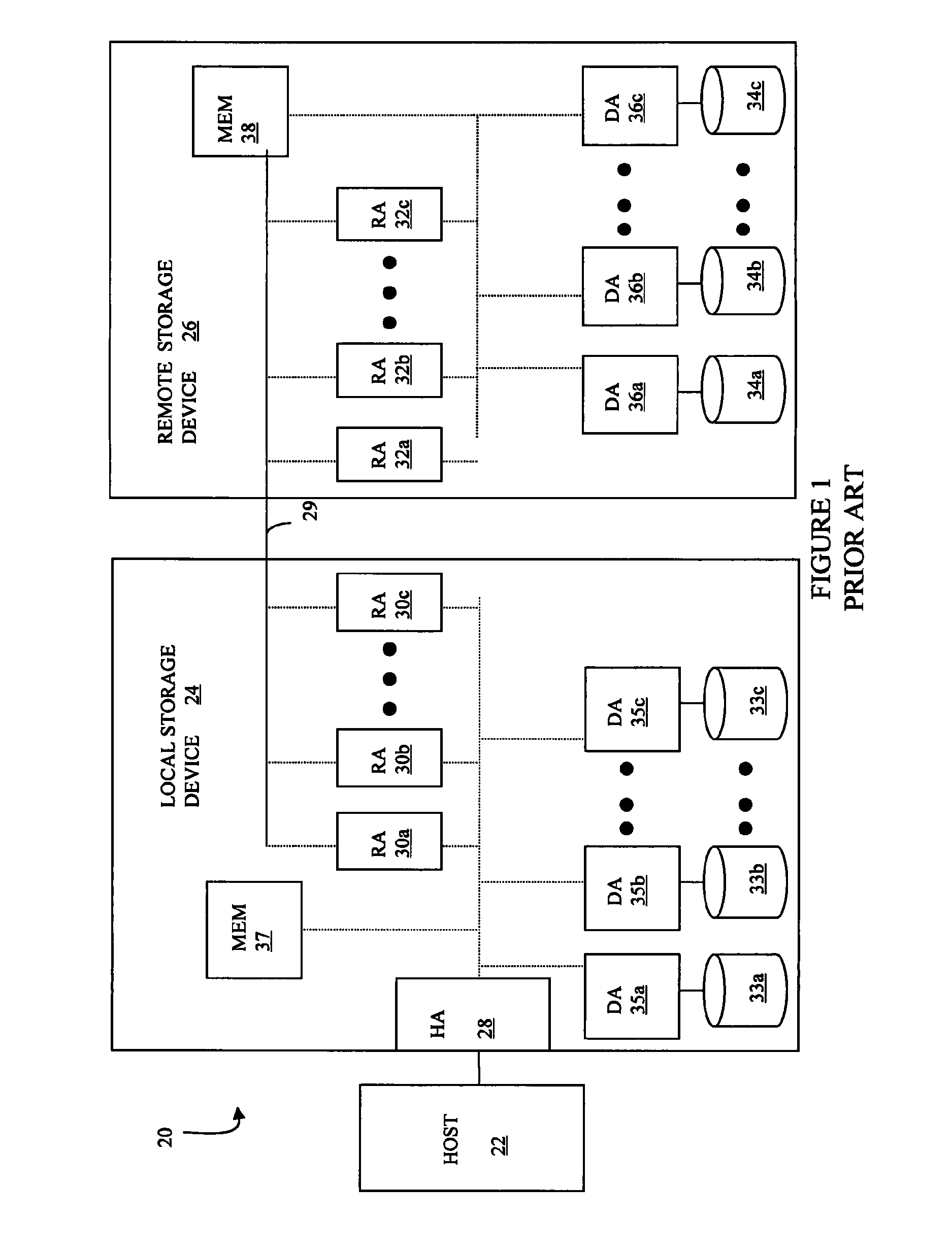
BACKGROUND OF THE INVENTION[0001]1. Technical Field[0002]This application relates to computer storage, and more particularly to the field of partitioning computer storage.[0003]2. Description of Related Art[0004]Host processor systems may store and retrieve data using a storage device containing a plurality of host interface units (host adapters), disk drives, and disk interface units (disk adapters). Such storage devices are provided, for example, by EMC Corporation of Hopkinton, Mass. and disclosed in U.S. Pat. No. 5,206,939 to Yanai et al., U.S. Pat. No. 5,778,394 to Galtzur et al., U.S. Pat. No. 5,845,147 to Vishlitzky et al., and U.S. Pat. No. 5,857,208 to Ofek, all of which are incorporated by reference herein. The host systems access the storage device through a plurality of channels provided therewith. Host systems provide data and access control information through the channels to the storage device and the storage device provides data to the host systems also through the c...

Claims


Application Information

Patent Timeline
Patent Type & Authority Patents(United States)
IPC IPC(8): G06F12/00
CPCG06F3/0607G06F3/0689G06F3/0664
Inventor MICHAEL, OFER E.SCHARLAND, MICHAEL J.VEPRINSKY, ALEXANDR
Owner EMC IP HLDG CO LLC
Learn More