Digital ADSL regenerator device with adaptive data forwarding

a technology of digital adsl and regenerator, applied in data switching networks, repeaters/relay circuits, baseband system details, etc., can solve the problems of network operators not being able to adjust the dlm profile of current regenerators, and the cost of this generally negates the cost advantage of using regenerators

Active Publication Date: 2019-08-20
BRITISH TELECOMM PLC
View PDF9 Cites 0 Cited by
  • Summary
  • Abstract
  • Description
  • Claims
  • Application Information

AI Technical Summary

Benefits of technology

[0064]With preferred embodiments, the configuration information may be received from the network operator by “re-using” one or more appropriately-selected existing DSL parameters that have little or no impact on DSL performance on a first DSL link but can serve to provide DLM configuration information to the management and control algorithms for a second (or subsequent) DSL link. This can be done without the need to configure and manage additional management channels to the regenerator or to the second (or subsequent) DSL link(s). By virtue of this, it becomes possible to perform DLM processing on regenerators and improve performance in respect of DSL links extending from regenerators while avoiding the cost and complexity of additional management channels.

Problems solved by technology

To allow remote links to be monitored and subjected to DLM, it would be possible to build monitoring and management channels to regenerators (with suitable OSS interconnections), but the cost of this generally negates the cost advantage of using regenerators.
Without such communication channels, current regenerators do not allow network operators to adjust the DLM profile for a customer-side link independently of the profile on the associated operator-side link, let alone in dependence on performance of the customer-side link (which is likely to differ from that of the associated operator-side link) according to a DLM algorithm that may be remotely reconfigured while in use by the operator.

Method used


Image

  • Digital ADSL regenerator device with adaptive data forwarding
  • Digital ADSL regenerator device with adaptive data forwarding
  • Digital ADSL regenerator device with adaptive data forwarding

Examples


Embodiment Construction

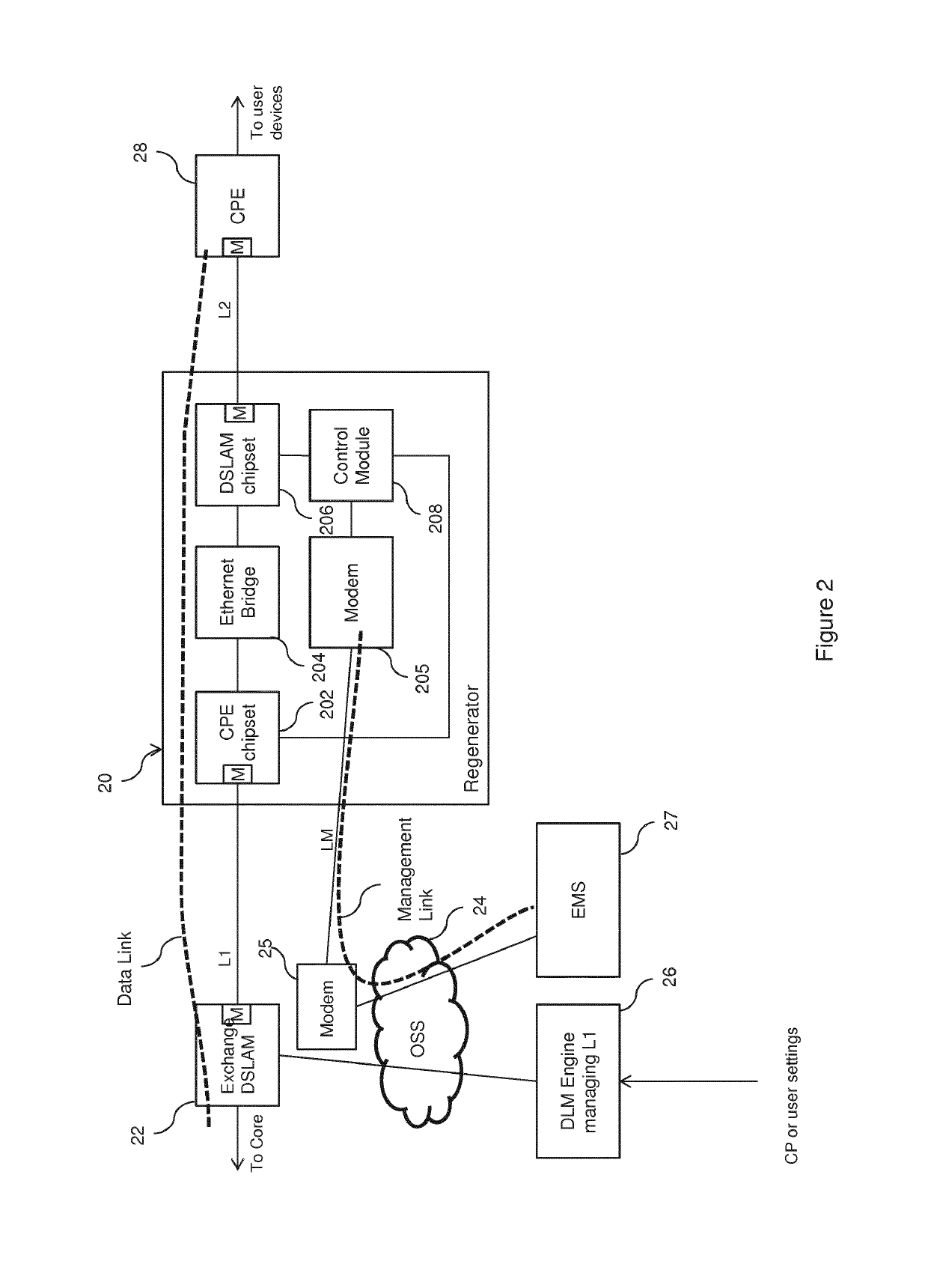
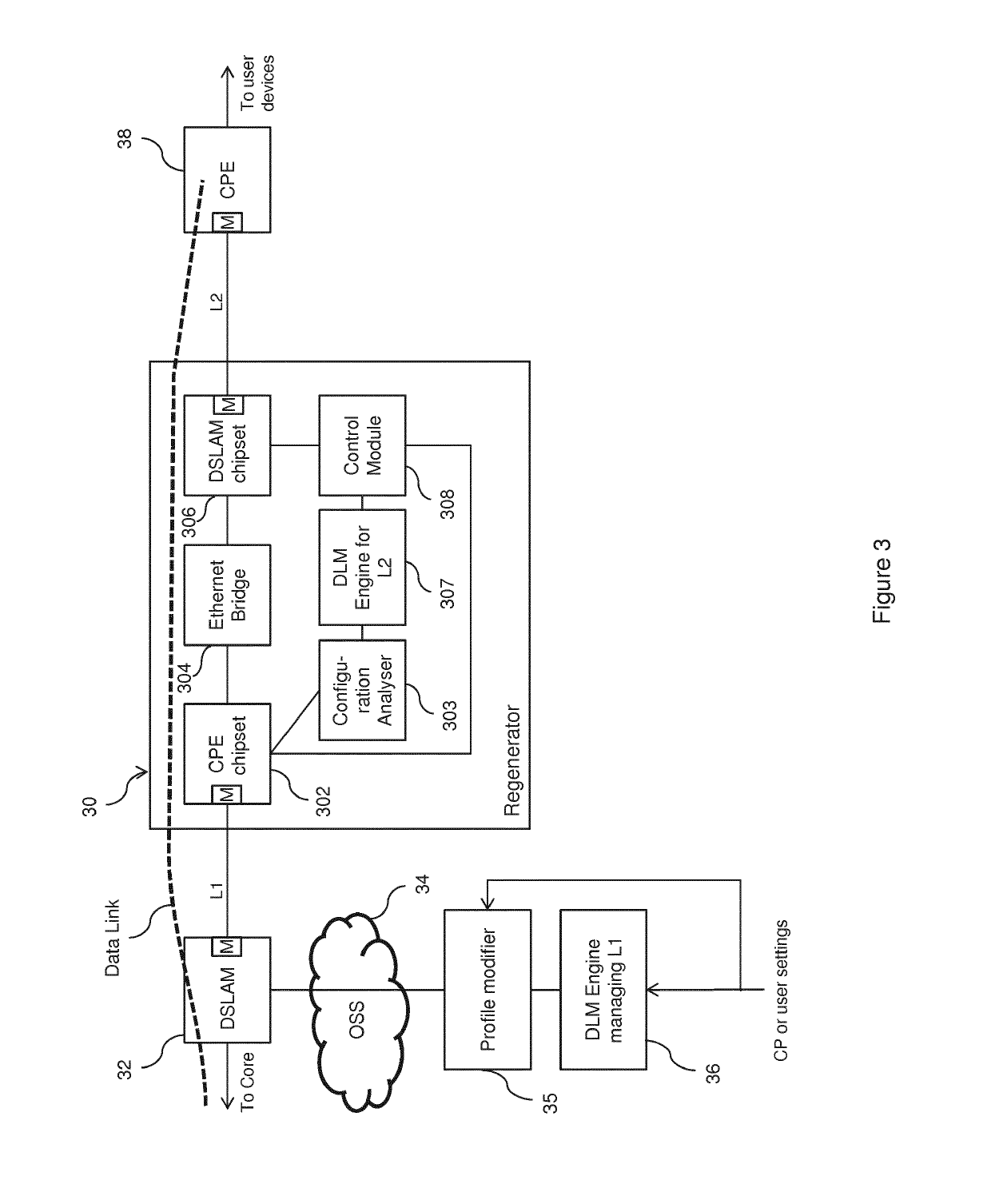
[0071]With reference to the accompanying figures (and in particular to FIGS. 3 and 4), regenerators according to preferred embodiments will be described, together with preferred manners in which such regenerators may operate. The description will explain in particular how DLM configuration information may be passed to and interpreted by a regenerator according to a preferred embodiment, used by a DLM Engine module on such a regenerator, and when required used to trigger a reset of the DLM profile and DLM Engine configuration on a customer-side DSL link extending from the regenerator to a customer (or towards a customer, in cases where there are multiple regenerators, for example).

[0072]For the purposes of this description, reference will be made principally to an implementation in the context of a VDSL2 line, but it will be understood that embodiments of the invention are applicable in the context of technologies other than VDSL2 (such as ADSL and variants thereof). In relation to t...


PUM


Abstract

Regenerator devices (30) for use with Digital Subscriber Line (DSL) connections are disclosed which forward user data received in a modulated signal from one link (L1) of a DSL connection on to another link (L2) of the DSL connection. Such devices comprise a first transceiver module (302) which receives a modulated signal from the first link and demodulates it whereby to obtain user data, and a second transceiver module (306) which receives the user data obtained by the first transceiver module and transmits a modulated signal carrying it on to the other link. The device further comprises a performance analyzer (308) which obtains performance information in respect of the second link, and a profile management processor (307) which determines a profile to be applied in respect of the second link in dependence on the performance information obtained in respect thereof. An access net work including one or more such devices and associated methods are also disclosed.

Description

[0001]This application is the U.S. national phase of International Application No. PCT / EP2015 / 069033 filed 19 Aug. 2015, which designated the U.S. and claims priority to GB Patent Application No. 1414679.9 filed 19 Aug. 2014, the entire contents of each of which are hereby incorporated by reference.TECHNICAL FIELD[0002]The present invention relates to regenerator devices for use with Digital Subscriber Line connections, to access networks including such devices, and to associated methods.BACKGROUND TO THE INVENTION AND PRIOR ART[0003]A Digital Subscriber Line (DSL) connection is a connection that allows for the provision of digital communication over an existing copper subscriber line. DSL is a collective term to cover a number of versions of DSL technology, including ADSL (“Asymmetric” DSL), SDSL (“Symmetric” DSL), ADSL2+(a technique that extends the capability of basic ADSL by doubling the number of downstream channels), VDSL (Very-high-bit-rate DSL), VDSL2 (an improved version of...

Claims


Application Information

Patent Timeline
Patent Type & Authority Patents(United States)
IPC IPC(8): H04M1/00H04L1/00H04B3/46H04B3/36H04M11/06H04B3/38H04L12/28H04L25/20H04M3/30H04L12/64
CPCH04L12/2869H04B3/36H04B3/38H04B3/46H04L25/20H04M11/062H04L1/0002H04M3/304H04L2001/0097H04L2012/6478H04L1/0001H04L5/0042H04L43/08
Inventor HORSLEY, IAN
Owner BRITISH TELECOMM PLC
Why Eureka
Try Eureka