
Method of measuring diffractive lenses

a technology of diffractive lenses and optical properties, applied in the field of multi-focal diffractive ophthalmic lenses, to achieve the effect of high resolution and determination of overall optical properties of lenses

Active Publication Date: 2011-05-17
ALCON INC
View PDF3 Cites 24 Cited by
  • Summary
  • Abstract
  • Description
  • Claims
  • Application Information

AI Technical Summary

Benefits of technology

Enables accurate measurement of optical properties across the lens surface, generating image quality parameters like modulation transfer function, and identifying beneficial or detrimental regions for optical performance, thus improving the evaluation and manufacturing of multifocal diffractive lenses.

Problems solved by technology

These systems are not specifically designed to evaluate a lens with more than one power, and, in particular, they are not designed to evaluate diffractive lenses with more than one power.

Method used


Image

  • Method of measuring diffractive lenses
  • Method of measuring diffractive lenses
  • Method of measuring diffractive lenses

Examples


Embodiment Construction

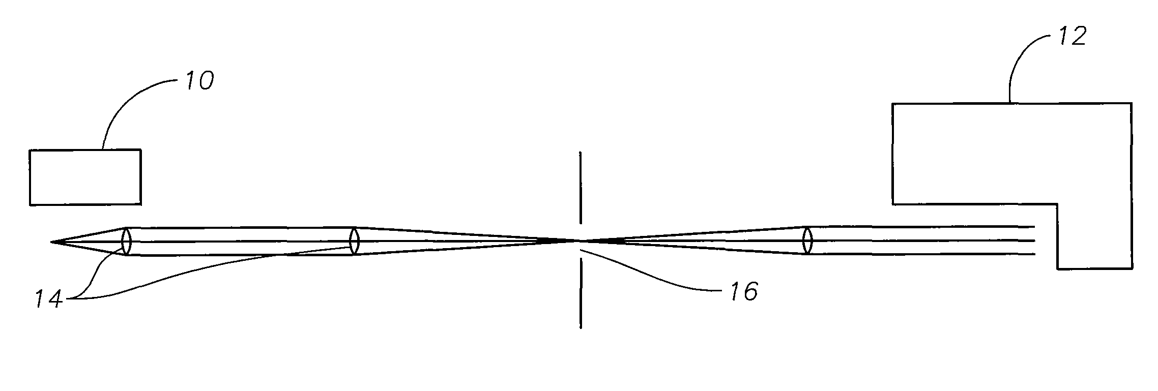
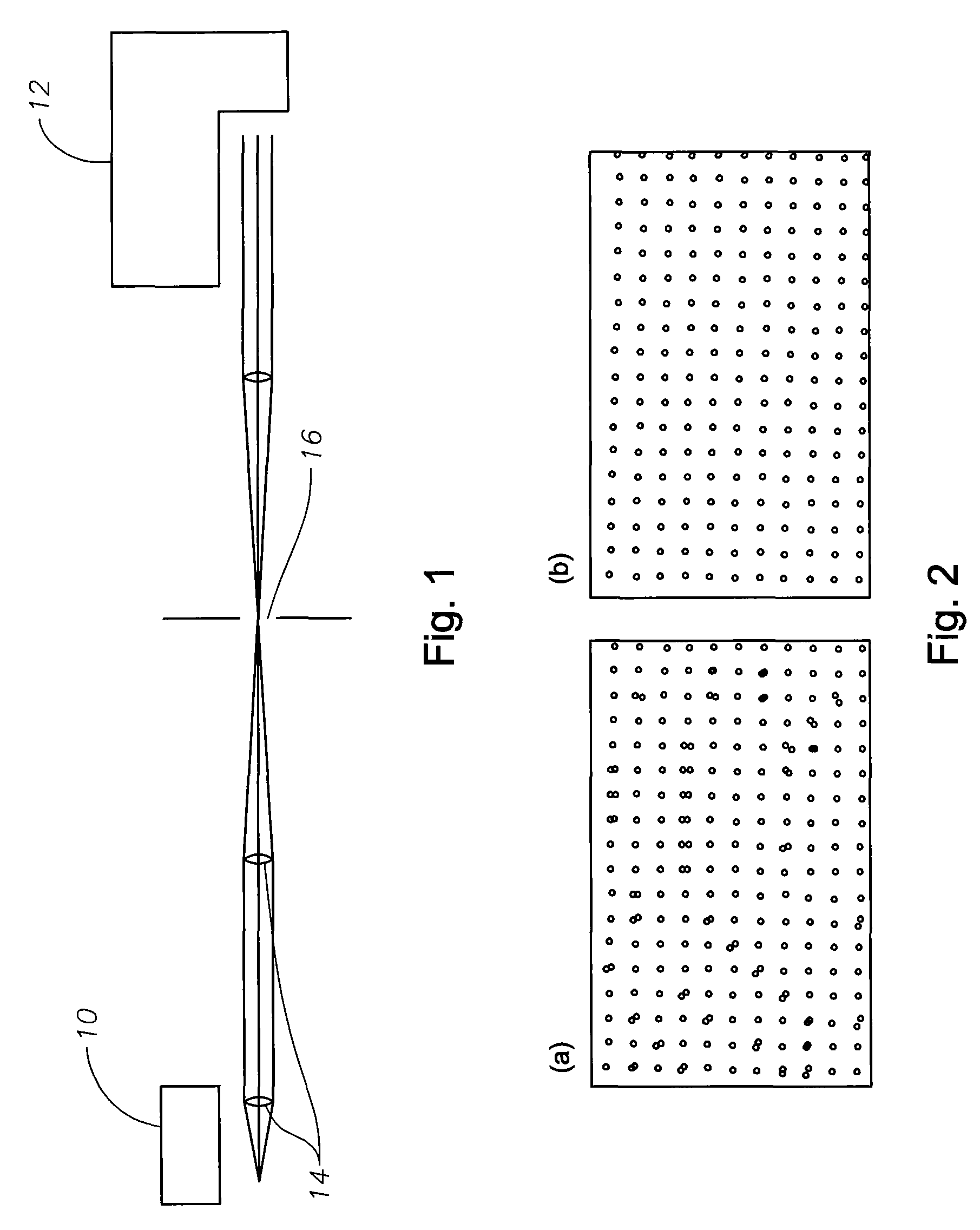
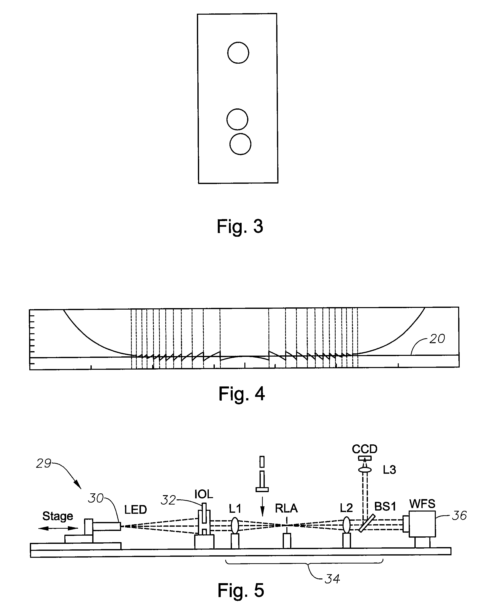
[0024]The embodiments of the present invention provide advantages over prior art lens measurement methods and systems in that wavefront measurements can provide information about the quality of an optical system at different locations across a lens. This information can be used to generate image quality parameters, such as modulation transfer function (“MTF”) or resolution, which describe properties that are useful in determining how an image might appear. The information is also of direct use for a lens manufacturer, or for anyone interested in improving an optical system composed of, for example, an eye and an intra-ocular lens (“IOL”), because it can be used to determine which regions of the IOL (lens) provide beneficial or detrimental contributions to optical performance of the system. For example, measurements of image quality can be used to indicate whether a lens is acceptable or unacceptable, but they do not evaluate the overall imaging characteristics of the lens. A wavefro...


PUM


Abstract

A method and system for measuring an optical property of a multi-focal lens are disclosed. One embodiment of the method comprises: filtering out light transmitted by all but one of a plurality of diffraction orders of the lens to provide an unfiltered light from a single diffraction order; receiving the unfiltered light at a wavefront detector; and analyzing the unfiltered light at the wavefront detector to measure the optical property. The multi-focal lens can be a multi-focal diffractive intra-ocular lens. The measured optical property can be a discontinuity in the lens surface. Filtering can comprise blocking all but the unfiltered light using an aperture operable to let through the unfiltered light from the single diffraction order, and / or blocking all but the unfiltered light using an opaque obstruction operable to let through only a selected amount of light corresponding to the light transmitted by the single diffraction order. The method can further comprise generating an image quality parameter, such as a modulation transfer function, based on the measured optical property.

Description

CROSS-REFERENCE TO RELATED APPLICATIONS[0001]This application is a continuation of U.S. patent application Ser. No. 11 / 564,498, filed Nov. 29, 2006 now U.S. Pat. No. 7,659,970, the entire contents of which are incorporated herein by reference, which claims priority to U.S. Provisional Patent Application No. 60 / 741,004, filed Nov. 30, 2005.TECHNICAL FIELD OF THE INVENTION[0002]The present invention relates generally to multifocal diffractive ophthalmic lenses and, more particularly, to a method of measuring the optical properties of a multifocal diffractive lens.BACKGROUND OF THE INVENTION[0003]Intraocular lenses are routinely implanted in a patient's eye during cataract surgery to compensate for the lost optical power that results when the natural lens is removed. In other applications, an intraocular lens can be implanted in a patient's eye, which retains its natural lens, so as to provide an optical power for correcting a refractive error of the natural eye. Many different types o...

Claims


Application Information

Patent Timeline
Patent Type & Authority Patents(United States)
IPC IPC(8): G01B9/00
CPCG01M11/0292
Inventor SIMPSON, MICHAEL J.XIE, JIHONG
Owner ALCON INC
Learn More