
Cochlear implant stimulation with variable number of electrodes

a technology of electrodes and cochlear implants, applied in the field of implant electrode stimulation, can solve the problems of spatial channel interaction, inability to choose the phase duration arbitrarily short, and the cochlear implant is not suitable for us

Active Publication Date: 2011-05-10
MED EL ELEKTROMEDIZINISCHE GERAETE GMBH
View PDF18 Cites 9 Cited by
  • Summary
  • Abstract
  • Description
  • Claims
  • Application Information

AI Technical Summary

Benefits of technology

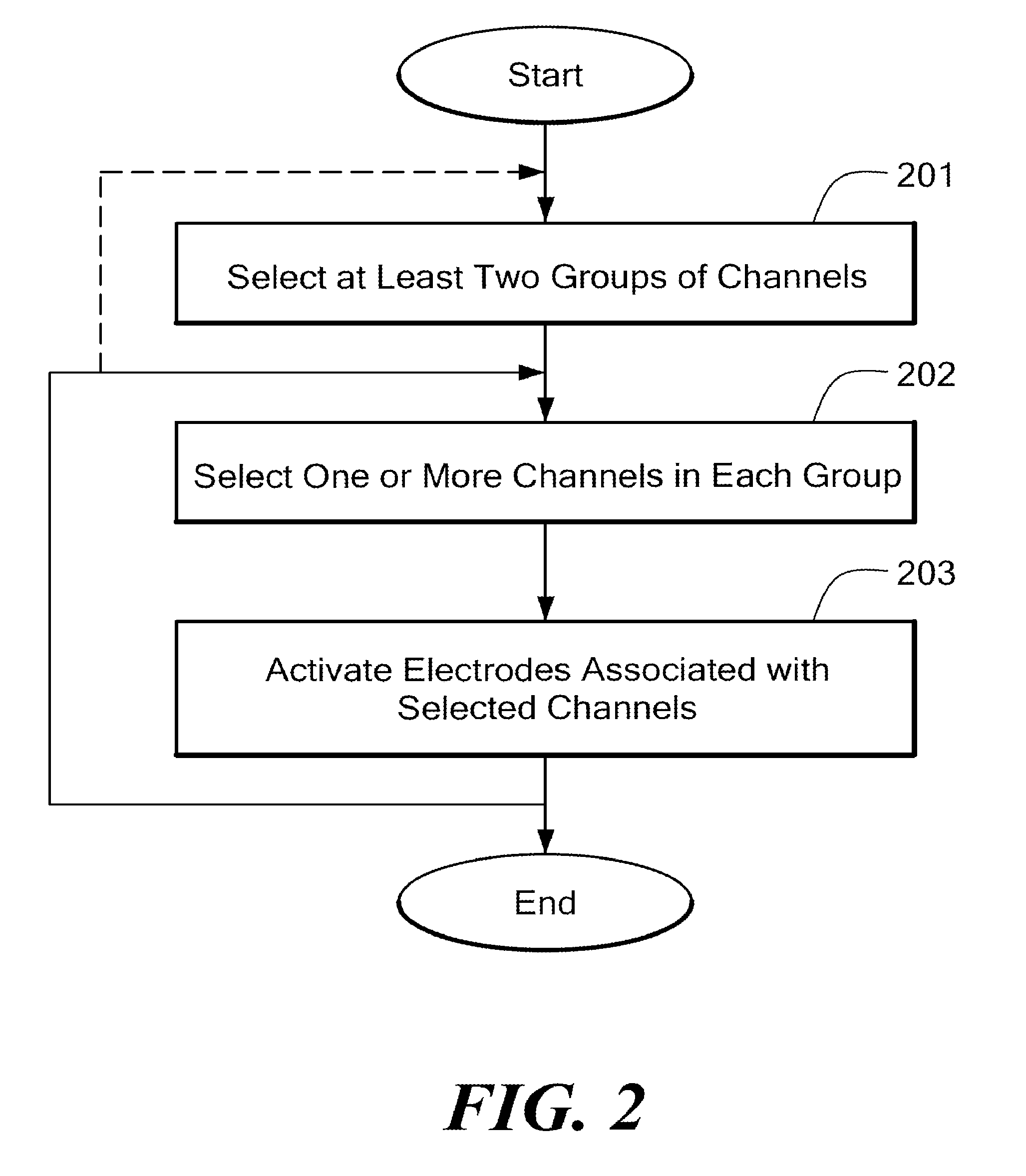
The present invention is about a system and method for activating electrodes in an implanted electrode array with a stimulation signal. The system assigns each electrode to one of multiple stimulation groups based on the characteristics of the sound signal. The electrodes are activated based on the spectral components of the stimulation signal and the location of the electrodes. The stimulation amplitude function for each stimulation group may reflect the non-linear response characteristics of the tissue stimulated by each electrode and the spatial interaction between the electrodes. The invention can be used in cochlear implant systems and other implant systems that use electrode stimulation.

Problems solved by technology

One problem in cochlear implants is spatial channel interaction.
The phase duration cannot be chosen arbitrarily short, because the shorter the pulses, the higher the current amplitudes have to be to elicit action potentials in neurons, and current amplitudes are limited for various practical reasons.
One disadvantage of N-of-M strategies (with constant M) is that neurons or ensembles of neurons may suffer “micro-shocks”, if electrode channels are switched from “inactive” to “active”.

Method used


Image

  • Cochlear implant stimulation with variable number of electrodes
  • Cochlear implant stimulation with variable number of electrodes
  • Cochlear implant stimulation with variable number of electrodes

Examples


example 1

Prior Art—“Conventional CIS”

[0031]In Example 1, selected groups in a conventional CIS system are shown in FIG. 3 (Prior Art). One CIS-stimulation cycle includes 12 selected groups 30. Each selected group 30 is composed of one channel. Since only one channel is present, it is the maximum itself (trivial case). Thus, this setting represents standard 12-channel CIS. The cycle repetition rate is R / 12.

example 2

Prior Art—“N-of-M”

[0032]In Example 2, one stimulation cycle using an N-of-M strategy contains only one selected group 40, which is composed of all 12 channels, as shown in FIG. 4 (Prior Art). The six channels with maximum energy are selected. Thus, this setting represents a conventional 6-of-12 setting. The cycle repetition rate is R / 6, which is an enhancement by a factor of 2 as compared to Example 1.

example 3

[0033]In Example 3, one stimulation cycle contains six selected groups 50, as shown in FIG. 5 in accordance with an embodiment of the invention. Each selected group comprises two channels, and the channel with the greatest amplitude is selected. The cycle repetition rate is R / 6 which is equal to example 2. However, an advantage over the N-of-M (example 2) is that permanent activity in all cochlear regions may be realized, comparable to standard CIS (Example 1). For example, in standard CIS, channels 1 and 2 are updated with a rate R / 12, respectively. Assuming considerable spatial channel interaction between neighboring channels, the “cochlear region” associated to channels 1 and 2 is thus updated on average by a rate of R / 6. In Example 3, one of the two channels 1 or 2 is selected, and thus the associated cochlear region is also updated with R / 6.


PUM


Abstract

A system and method for activating electrodes in an implanted electrode array with a stimulation signal is described. A stimulation definition stage, for each of a plurality of defined sound signal characteristics (C), assigns each electrode to one of a plurality of stimulation groups (G) each having an associated group stimulation amplitude function (A), where (G) varies with (C). An electrode stimulator activates each electrode as the stimulation signal varies based on spectral components of the stimulation signal.

Description

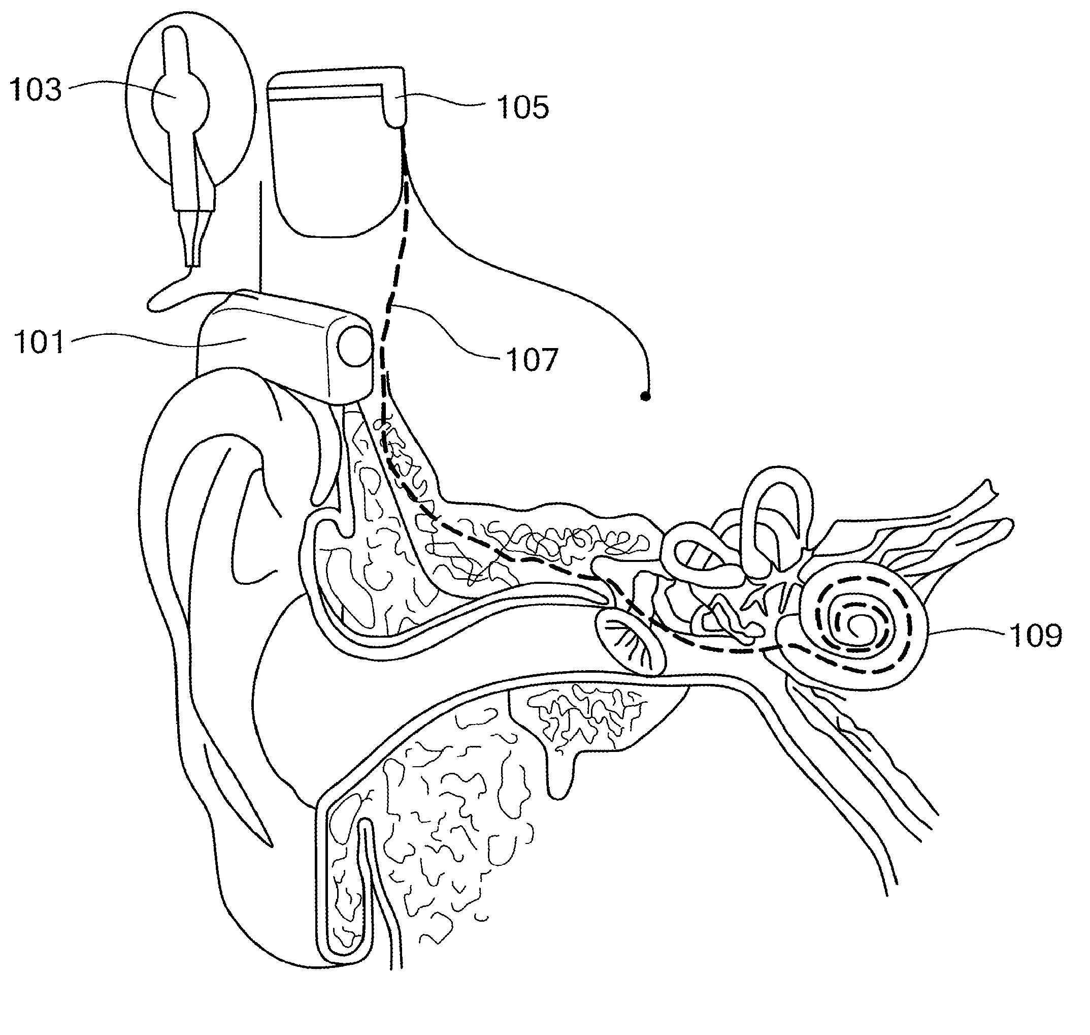
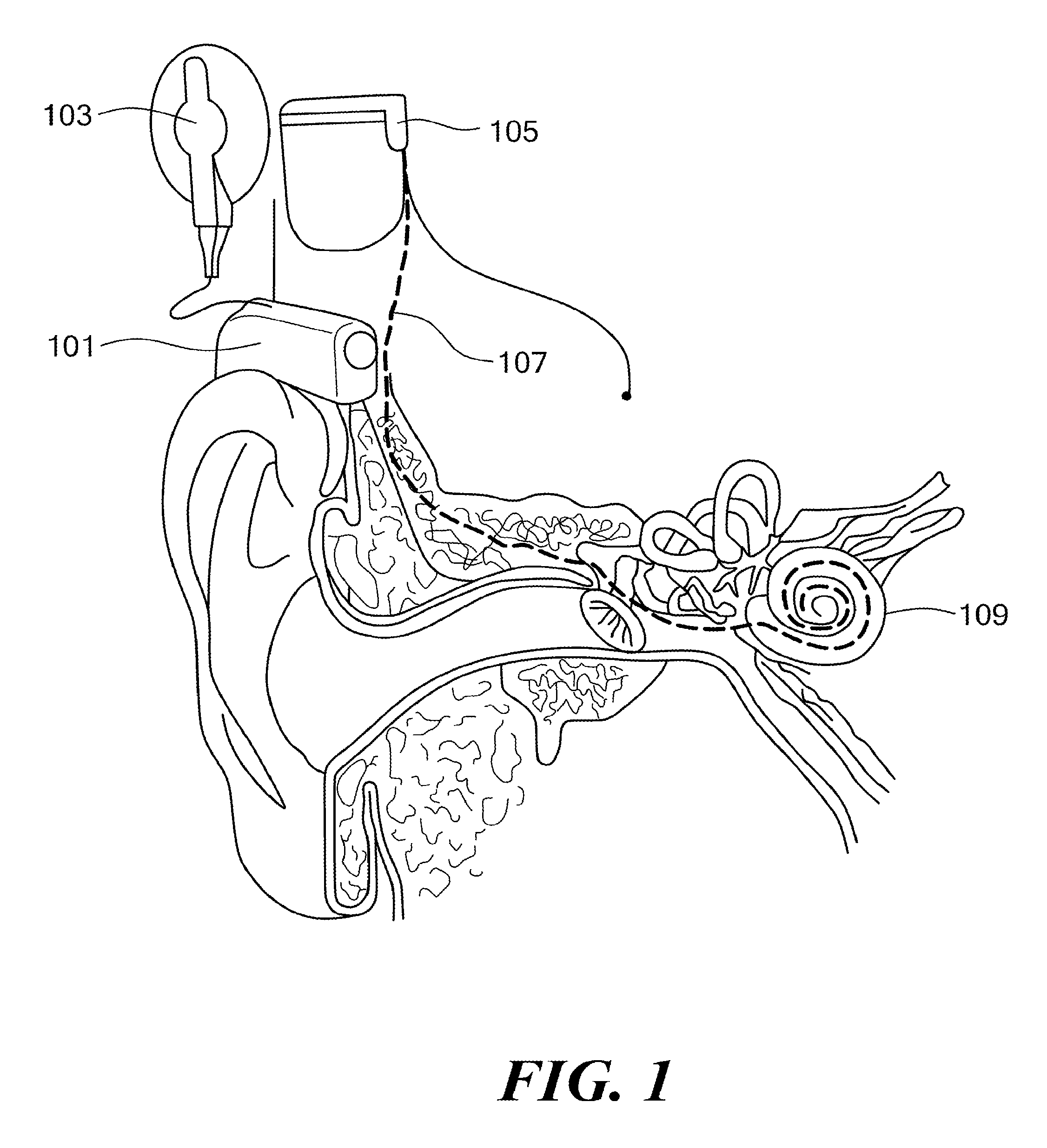
[0001]This application is a continuation-in-part of co-pending U.S. application Ser. No. 11 / 076,446, filed Mar. 8, 2005, which in turn claimed priority from U.S. Provisional Patent Application 60 / 551,318, filed Mar. 8, 2004; the contents of all of which are hereby incorporated by reference.FIELD OF THE INVENTION[0002]The present invention relates to implant electrode stimulation, and more particularly, a stimulation strategy that varies the number of electrodes stimulated.BACKGROUND ART[0003]Cochlear implants can provide hearing to profoundly deaf or severely hearing impaired persons. Unlike conventional hearing aids which mechanically apply an amplified sound signal to the middle ear, a cochlear implant provides direct electrical stimulation to acoustic nerve in the inner ear. Of course, it is desired that the created hearing sensation be as natural as possible.[0004]FIG. 1 shows a typical cochlear implant system. An external speech processor 101 that is positioned by the outer ear...

Claims


Application Information

Patent Timeline
Patent Type & Authority Patents(United States)
IPC IPC(8): A61N1/18
CPCA61N1/36032A61N1/36038
Inventor ZIERHOFER, CLEMENS M.NOPP, PETERSCHLEICH, PETERNOBBE, ANDREAASCHBACHER, ERNST
Owner MED EL ELEKTROMEDIZINISCHE GERAETE GMBH
Learn More