
Vehicle frame structure

a frame structure and vehicle technology, applied in the direction of roofs, movable seats, transportation and packaging, etc., can solve the problem that the footrest is not easily flexed, and achieve the effect of enhancing rigidity of the dash panel, facilitating large load acting on the footrest, and improving the degree of freedom in dash panel design

Active Publication Date: 2011-05-10
HONDA MOTOR CO LTD
View PDF14 Cites 23 Cited by
  • Summary
  • Abstract
  • Description
  • Claims
  • Application Information

AI Technical Summary

Benefits of technology

[0012]As an effect, the partly curved dash panel enhances the rigidity of the dash panel itself.
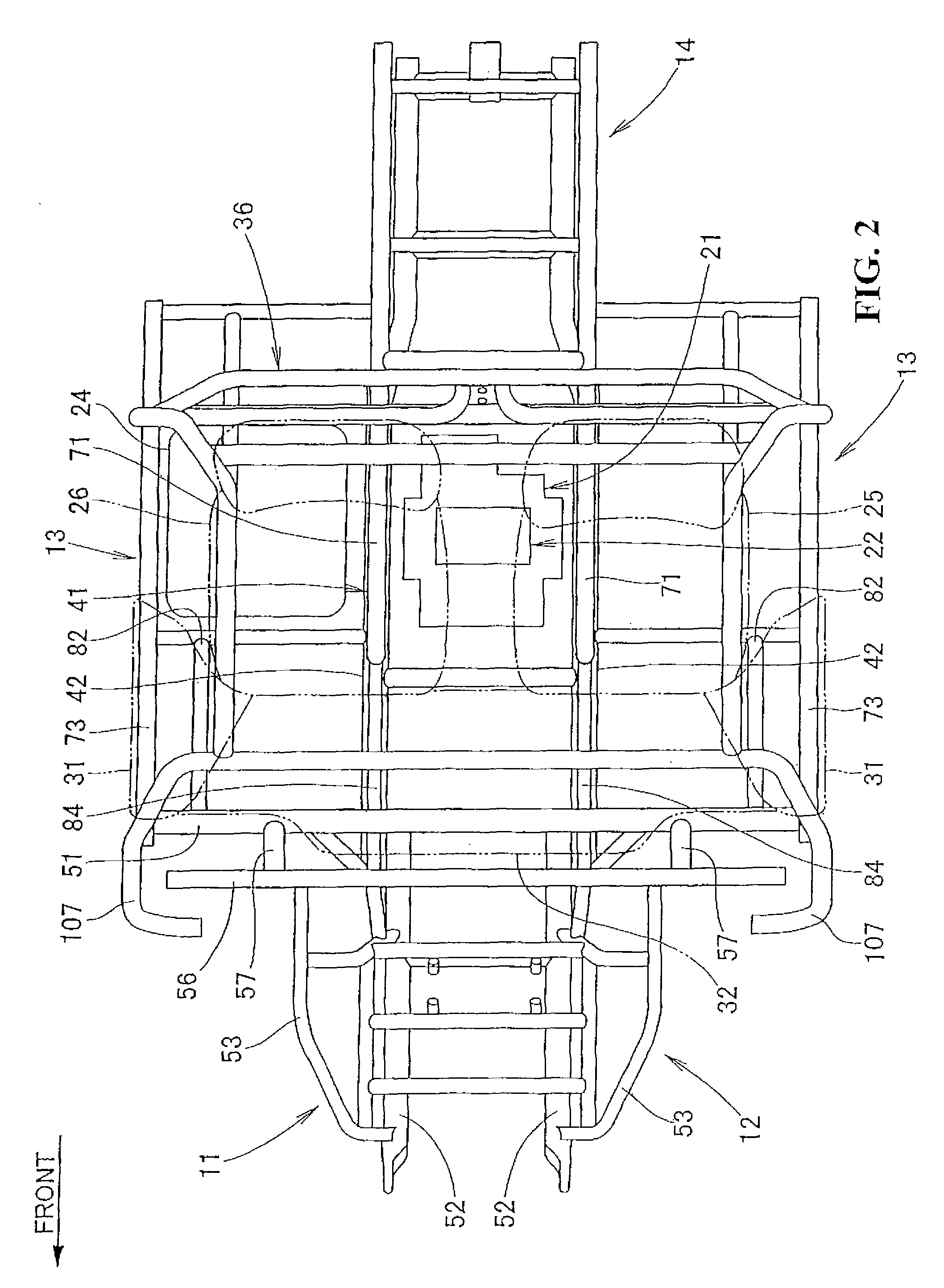
[0015]In accordance with an embodiment of the present invention, the foot operation zone and the footrest are disposed between the lower cross member, disposed so as to extend laterally across the front ends of the pair of left and right lower main frames, and the upper cross member, disposed upward of and in parallel with the lower cross member, and the connection frame connecting the lower cross member with the upper cross member is disposed between the foot operation zone and the footrest. This allows the connection frame to receive foot pressure acting on the footrest. When the driver rests his or her foot on the footrest to support his or her body during driving, a large load acting on the footrest can be received.
[0016]In accordance with an embodiment of the present invention, the bulkhead is formed by curving part of the dash panel between the foot operation zone and the footrest and the connection frame is disposed inside the bulkhead. The partly curved dash panel enhances rigidity of the dash panel. This also helps the footrest receive a large load. A boundary between the foot operation zone and the footrest is thus made clear, allowing the driver to deploy his or her feet easily.
[0017]In accordance with an embodiment of the present invention, there is no frame involved connecting both ends of the lower cross member and the upper cross member, though the portions across both ends of the lower cross member and the upper cross member are covered with the dash panel. This improves a degree of freedom in design of the dash panel.

Problems solved by technology

The footrest is not therefore easily flexed even by a large pressure applied thereto.

Method used


Image

  • Vehicle frame structure
  • Vehicle frame structure
  • Vehicle frame structure

Examples


Embodiment Construction

[0035]The best mode for carrying out the present invention will be described below with reference to the accompanying drawings. The drawings should be viewed in the direction of reference numerals.

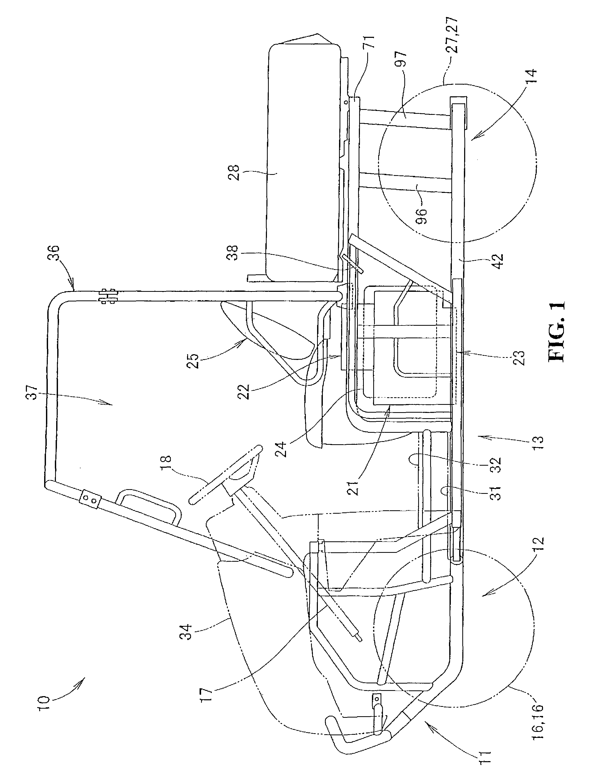
[0036]FIG. 1 is a side elevational view showing a vehicle incorporating a frame structure according to an embodiment of the present invention. A vehicle 10 is an all terrain vehicle with a vehicle body frame 11 that includes a front frame 12, a center frame 13, and a rear frame 14. The front frame 12 includes a front wheel suspension (not shown), disposed thereon, for suspending left and right front wheels 16, 16. The front frame 12 further includes steering members (a steering shaft 17, a steering wheel 18 disposed on an upper end of the steering shaft 17, and the like) for steering the front wheels 16. The center frame 13 is mounted with a power unit 21 (including an engine 22 and a transmission 23 integrated with the engine 22), a fuel tank 24, and left and right seats 25, 26 (only refe...


PUM


Abstract

A vehicle frame structure allowing a footrest to support an even larger force. A foot operation zone and a driver's footrest are disposed between a lower cross member disposed so as to extend laterally across front ends of a pair of left and right lower main frames and an upper cross member disposed upward of, and extending in parallel with, the lower cross member. Connection frames connecting the lower cross member with the upper cross member are disposed between the foot operation zone and the driver's footrest.

Description

CROSS-REFERENCE TO RELATED APPLICATIONS[0001]The present application claims priority under 35 USC 119 to Japanese Patent Application No. 2007-226634 filed on Aug. 31, 2007 the entire contents of which are hereby incorporated by reference.BACKGROUND OF THE INVENTION[0002]1. Field of the Invention[0003]The present invention relates to an improved frame structure for a vehicle.[0004]2. Description of Background Art[0005]A vehicle is known that includes a floor portion on which an occupant can place his or her feet. See, for example, Japanese Patent Laid-Open No. 2006-103370.[0006]FIG. 1 of Japanese Patent Laid-Open No. 2006-103370 includes a vehicle 10 with a floor portion 32 disposed on a lower portion of a cabin. When an occupant gets on or off the vehicle 10 or sits on a seat 25 to drive the vehicle 10, he or she places his or her feet on the floor portion 32.[0007]When the occupant operates an accelerator pedal or a brake pedal with his / her right foot, he or she has his / her left fo...

Claims


Application Information

Patent Timeline
Patent Type & Authority Patents(United States)
IPC IPC(8): B62D25/20
CPCB60N2/22B60N3/06B62D25/14B62D31/003B62D21/186B60N2002/684B60N2/015
Inventor KOBAYASHI, TAKESHIINOUE, MASAHIRO
Owner HONDA MOTOR CO LTD
Learn More