
Efficient exploding foil initiator and process for making same

a foil initiator and efi technology, applied in the field of actuators, can solve the problems of reducing efi efficiency, reliability, longevity, inefficient and expensive, inconvenient operation, etc., and achieves the effects of reducing energy requirements, facilitating mass production, and increasing efi reliability

Inactive Publication Date: 2011-05-10
DESAI AMISH
View PDF6 Cites 7 Cited by
  • Summary
  • Abstract
  • Description
  • Claims
  • Application Information

AI Technical Summary

Benefits of technology

"The patent text describes an actuator assembly that includes a substrate with a bridge and a lithographically disposed flyer. The actuator assembly also includes a lithographically disposed barrel and a fireset. The actuator assembly can be made using lithographical processes, which allow for mass production of precise and small components. The design of the actuator assembly can be tailored to specific requirements, such as reducing energy requirements and alleviating design constraints on accompanying systems. The technical effects of the patent text include improved reliability, reduced energy requirements, and smaller firesets."

Problems solved by technology

Safe initiators are particularly important in munitions applications, where inadvertent activation of an explosive charge can be devastating.
Unfortunately, conventional EFIs are often bulky, inefficient, and expensive.
Certain EFI design constraints may necessitate individually constructed EFIs with hand-placed or machine-placed components, such as flyers, barrels, and electrodes that electrically couple the firesets to the bridges.
Such manually placed discrete components are prone to misalignment relative to the foil and may dislodge or move over time, which reduces EFI efficiency, reliability, and longevity.
For example, a misplaced flyer and barrel may result in a misguided flyer that reduces the effectiveness of the flyer in detonating the explosive charge.
Complicated and expensive machines and processes may be required to accurately position discrete EFI components.
In addition, discretely placed components are often prone to undesirable movement or displacement in response to shock or vibration, which may occur, for example, during missile flight.
Furthermore, the EFIs may require excessively large and expensive firesets to produce sufficient voltage and flyer velocity to compensate for inaccuracies in EFI-component placement and design inefficiencies.
Unfortunately, such EFIs generally still require manual or machine placement of discrete components, resulting in expensive and error-prone EFIs.

Method used


Image

  • Efficient exploding foil initiator and process for making same
  • Efficient exploding foil initiator and process for making same
  • Efficient exploding foil initiator and process for making same

Examples


first embodiment

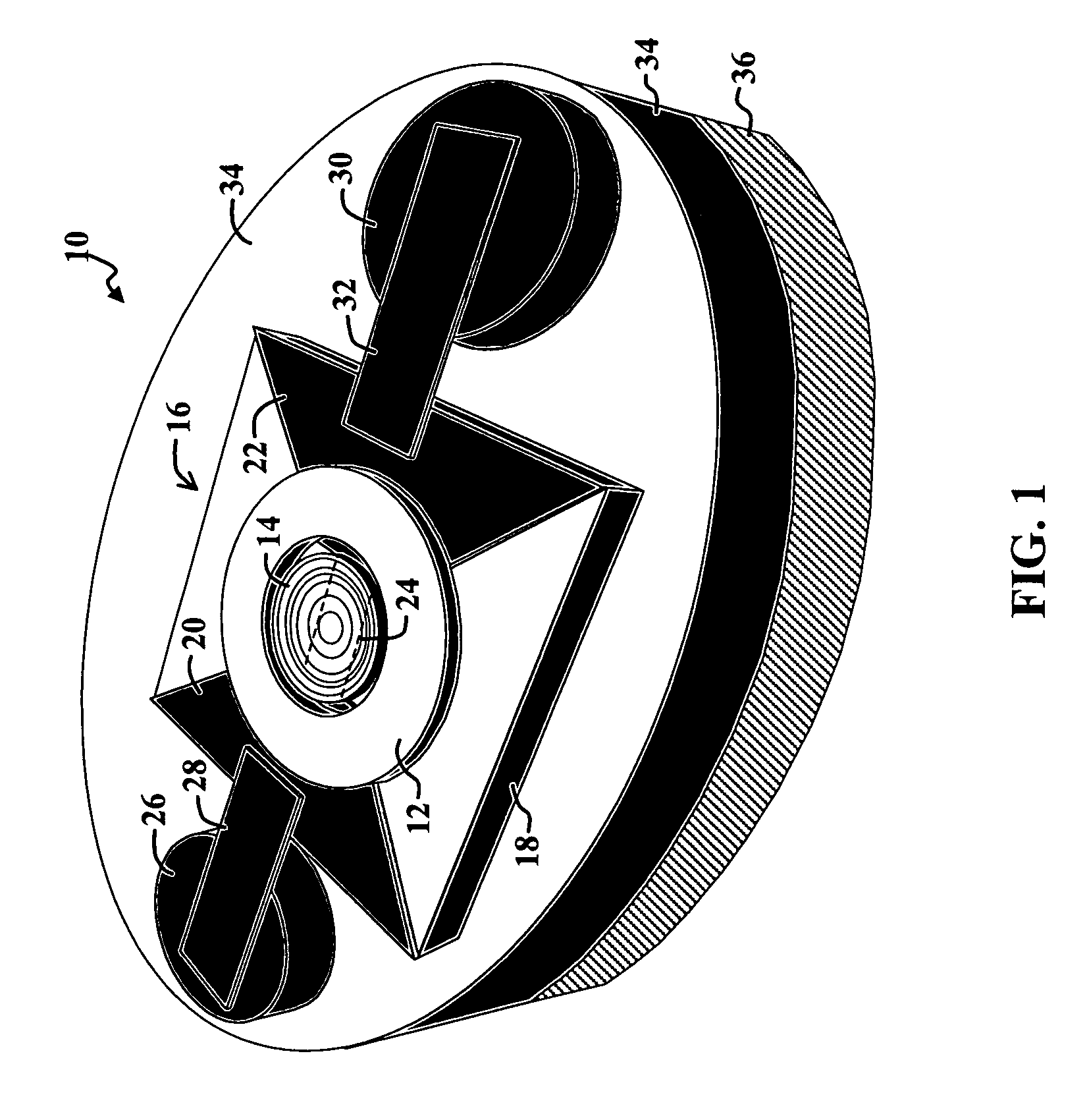
[0031]FIG. 1 is a diagram of an Exploding Foil Initiator (EFI) 10 which employs a lithographically formed barrel 12 and concave flyer 14 disposed on a flyer assembly 16. For the purposes of the present discussion, an EFI may be any initiator that uses a bridge or exploding foil, also called an expanding foil, to generate kinetic energy or to otherwise launch a projectile, such as a flyer, to initiate an action. While various flyer shapes are discussed herein, including concave, convex, and star-shaped flyers, such examples are not intended to be limiting. For example, the concave flyer 14 may be replaced with a substantially flat or square flyer without departing from the scope of the present teachings.

[0032]The flyer assembly 16 includes a first substrate 18 upon which is disposed a first electrode 20 and a second electrode 22, which are also called lands. The first electrode 20 and second electrode 22 are electrically coupled via a bridge 24, the boundaries of which are shown via...

second embodiment

[0052]FIG. 2 is a diagram of an EFI assembly 46 which includes a lithographically formed convex flier 44 and includes contact pins 56, 60 that directly contact lands 50, 52 of the EFI assembly 46.

[0053]The construction and operation of the EFI assembly 46 are similar to the construction and operation of the EFI assembly 16 of FIG. 1 with various exceptions. In particular, the substrate 18 of the EFI assembly 16 of FIG. 1 is replaced with a PCB substrate 48 in the EFI assembly 46 of FIG. 2. In addition, the barrel 12 of FIG. 1 is replaced with a tabbed barrel 42 in FIG. 2, which has a first tab 62 and a second tab 64 extending therefrom. Furthermore, the first pin 26 and second pin 30 of FIG. 1 are replaced with a third pin 56 a fourth pin 60 in FIG. 2, respectively. The pins 56, 60 directly contact a third land 50 and a fourth land 52, respectively, and extend through the substrate 48 to a fireset, which is not shown in FIG. 2. In addition, the concave flyer 14 of FIG. 1 is replace...

third embodiment

[0074]FIG. 3 is a diagram of an EFI assembly 76 which includes a lithographically formed strategically perforated flyer 74 with contact pins 56, 60 that directly contact the lands 50, 52 of the EFI assembly 76.

[0075]The construction and operation of the EFI assembly 76 are similar to the construction and operation of the EFI assembly 46 of FIG. 2 with various exceptions. In particular, the convex flyer 44 of FIG. 2 is replaced with the strategically perforated flyer 74 in FIG. 3. Furthermore, the ring-shaped bridge 54 of FIG. 2 is replaced with a rectangular bridge 84 in FIG. 3

[0076]The strategically perforated flyer 74 includes a first set of perforations 78, which are approximately centered on the perforated flyer 74. Several sets of smaller perforations 80 are positioned near the outer edges of the perforated flyer 74. The exact placement of the perforations 78, 80 may be altered, and different shapes, sizes, and arrangements of perforations may be altered without departing from...


PUM


Abstract

An actuator assembly that includes, in one example embodiment, a substrate with a bridge coupled between a first electrode and a second electrode on the substrate. A lithographically disposed flyer is positioned in proximity to the bridge. In a more specific embodiment, the actuator assembly further includes a lithographically disposed barrel that partially surrounds the flyer. A fireset is coupled to pins that extend through the substrate to the first electrode and the second electrode. The flyer further includes a three-dimensional surface adapted to flatten during flight. The flyer may be concave, convex, or may star shaped, may have perforations therein, or may exhibit another shape or other features.

Description

ACKNOWLEDGEMENT OF GOVERNMENT SUPPORT[0001]This invention was made with Government support under Contract No. W15QKN-04-C-1130 awarded by US ARMY TACOM-ARDEC. The Government has certain rights to this invention.CROSS-REFERENCE TO RELATED APPLICATIONS[0002]This application is related to co-pending U.S. patent application Ser. No. 60 / 772,180 filed on May 7, 2007, entitled MULTILAYERED MICROCAVITIES AND ACTUATORS INCORPORATING SAME, which is hereby incorporated by reference as if set forth in full in this application.[0003]This application is related to U.S. Pat. No. 7,021,217, issued Apr. 4, 2006, entitled VERSATILE CAVITY ACTUATOR AND SYSTEMS INCORPORATING SAME, which is hereby incorporated by reference as if set forth in full in this application.BACKGROUND OF THE INVENTION[0004]1. Field of Invention[0005]This invention relates to actuators. Specifically, the present invention relates to devices and components thereof for selectively initiating an action and further relates to method...

Claims


Application Information

Patent Timeline
Patent Type & Authority Patents(United States)
IPC IPC(8): F23Q7/02
CPCF42B3/121
Inventor DESAI, AMISH
Owner DESAI AMISH
Learn More