Image processing device and image processing method
a technology of image processing and image processing, applied in the field of image processing device and image processing method, can solve the problems of not enabling the classification of shadows which appear when no light source is moved, and a large-scale device, and achieves the effect of easy extraction of attached shadow areas and casting shadow areas, high refinement of images, and high practicality
- Summary
- Abstract
- Description
- Claims
- Application Information
AI Technical Summary
Benefits of technology
Problems solved by technology
Method used
Image
Examples
embodiment 1
[0080]First, a description is given of the outline of the optical area dividing device in Embodiment 1 of the present invention.
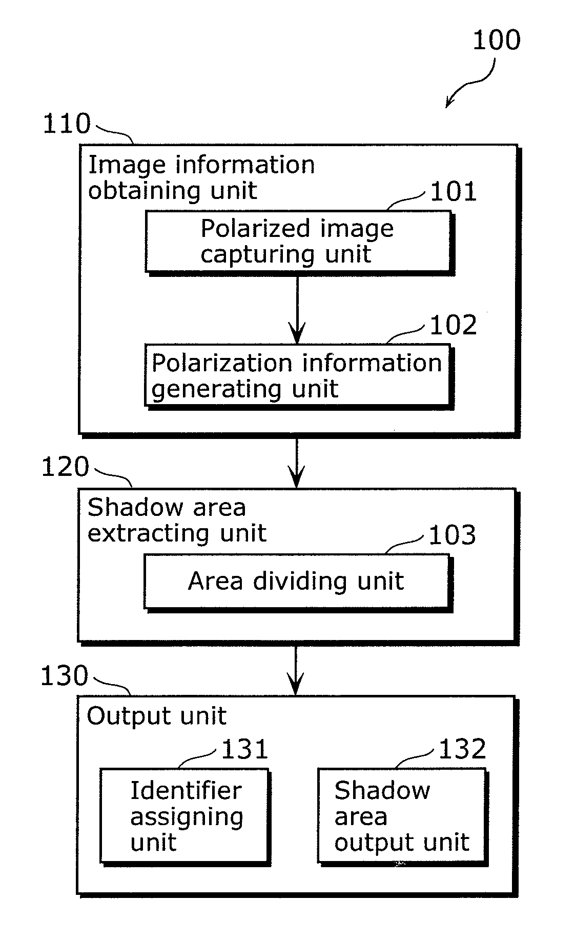
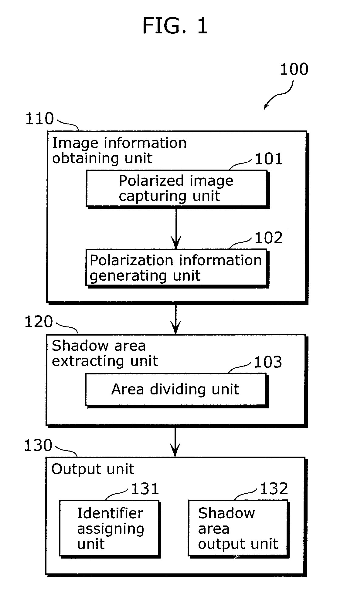
[0081]FIG. 1 is a functional block diagram showing the structure of the optical area dividing device 100 in this Embodiment. The optical area dividing device 100 is an example of the image processing device which performs processing on a shadow in the image of the object. Here, the optical area dividing device 100 is a device for performing optical area division on the surface of the object by imaging the object, and includes an image information obtaining unit 110, a shadow area extracting unit 120, and an output unit.
[0082]The image information obtaining unit 110 is a processing unit for obtaining information related to an object image including luminance information about luminance of light from the object, and polarization information about polarization of light from the object, and includes a polarized image capturing unit 101 and a polarization inform...
embodiment 2
[0192]Next, a description is given of an optical area dividing device in Embodiment 2 of the present invention.
[0193]FIG. 32 is a functional block diagram showing the structure of the optical area dividing device 100b in this Embodiment. This optical area dividing device 100b is a device for performing optical area division on the surface of an object by imaging the object, and is characterized by classifying low luminance areas into “attached shadow areas or low reflectance areas” and cast shadow areas. This optical area dividing device 100b includes an area dividing unit 1031 instead of the area dividing unit 103 in the optical area dividing device 100 shown in FIG. 1. Here, the normal vector information generating unit 1041 is also shown in this example of processing in which the result of processing by the optical area dividing device 100b is used. Although the normal vector information generating unit 1041 is not an essential structural element of the image processing device ac...
embodiment 3
[0214]Next, a description is given of an optical area dividing device in Embodiment 3 of the present invention.
[0215]FIG. 37 is a functional block diagram showing the structure of the optical area dividing device 100c in this Embodiment. This optical area dividing device 100c is a device for performing optical area division on the surface of an object by imaging the object, and is characterized by generating normal vector information only when accurate normal vector information can be generated. This optical area dividing device 100c includes an imaging condition judging unit 106 in addition to the structure of the optical area dividing device 100 shown in FIG. 1. Here, a normal vector information generating unit 104 is also shown in this example of processing in which the result of processing performed by the optical area dividing device 100c is used. Although this normal vector information generating unit 104 is not an essential element of the image processing device according to ...
PUM
 Abstract
Description
Claims
Application Information
 - R&D
- Intellectual Property
- Life Sciences
- Materials
- Tech Scout
- Unparalleled Data Quality
- Higher Quality Content
- 60% Fewer Hallucinations
Browse by: Latest US Patents, China's latest patents, Technical Efficacy Thesaurus, Application Domain, Technology Topic, Popular Technical Reports.
© 2025 PatSnap. All rights reserved.Legal|Privacy policy|Modern Slavery Act Transparency Statement|Sitemap|About US| Contact US: help@patsnap.com


