
Antenna diversity system for radio reception for motor vehicles

a technology for radio reception and antennas, applied in the direction of spatial transmit diversity, polarisation/directional diversity, transmission, etc., can solve the problems of interference, inability to achieve sufficient diversity effect, and limited function of same-phase summation of antenna signals, etc., to achieve cost-advantageous automobile construction

Inactive Publication Date: 2011-05-03
DELPHI DELCO ELECTRONICS EUROPE GMBH
View PDF92 Cites 19 Cited by
  • Summary
  • Abstract
  • Description
  • Claims
  • Application Information

AI Technical Summary

Benefits of technology

"The invention is a design for an antenna diversity system that is cost-effective and highly efficient. It requires only one high-frequency line to the receiver, while having multiple antennas. This design offers the advantages of phase superimposition of antenna signals, which include good signal / noise ratio and minimized interference. It can be used for car radio reception and offers the benefits of antenna selection and signal superimposition in a separate module. This module is positioned close to a multi-antenna system, making it easy to handle and cost-advantageous for automobile construction."

Problems solved by technology

However, perfect functioning of a same-phase summation of antenna signals is limited due to the fact that the partial waves that are superimposed at the reception location (Rayleigh reception field) differ only insignificantly in their momentary frequency.
These swings frequently result in interference that occurs spontaneously, after frequency demodulation while driving.
Another disadvantage of a purely phase-regulated system is the restriction to two antenna signals, so that there is no sufficient diversity effect achievable with this system.
Adjacent channel interference acts in similar manner, due to a limited selection in the inter-frequency plane.
Also, signals that occur in the reception channel due to intermodulation of other ultra-short-wave transmitters result in frequency swing interference on the useful signal, in combination with level collapses.
This interference cannot be eliminated using the phase regulation system with the same phasing.
However, the arrangement indicated in EP 1 126 631 has the remaining disadvantage of the occurrence of same channel or adjacent channel interference caused by undesired radio stations.
These undesired radio stations frequently form a cause for interference, because of the close frequency occupation with stations.
Thus, level maximization by means of the same phasing of the desired signal generally does not eliminate the interference phenomenon.
Another particular disadvantage of the arrangement indicated in EP 1 126 631 is in the practical implementation, which generally makes it necessary, for cost-advantageous implementation, for the phase regulation device to be accommodated in the receiver, and therefore at least two separate antenna lines must be brought to the receiver.
In automobile construction, this means increased expense and added required space, and is classified as disadvantageous with regard to vehicle handling.
As another disadvantage of the phase regulation device, there are, in the Rayleigh field, deep signal collapses, which the regulation device cannot follow, particularly when driving fast, and it must perform transient oscillation on them, thereby causing uncontrolled phase control with interference frequency swings to occur.
This in turn can result in interference in reception, on the basis of the frequency demodulation.
However, the great expenditure of material, which results from the second high-frequency line to the receiver, in combination with the need to require a second tuner circuit in the receiver, for the diversity function, is particularly serious for the economic efficiency of the solution indicated in EP 1 126 631.

Method used


Image

  • Antenna diversity system for radio reception for motor vehicles
  • Antenna diversity system for radio reception for motor vehicles
  • Antenna diversity system for radio reception for motor vehicles

Examples


Embodiment Construction

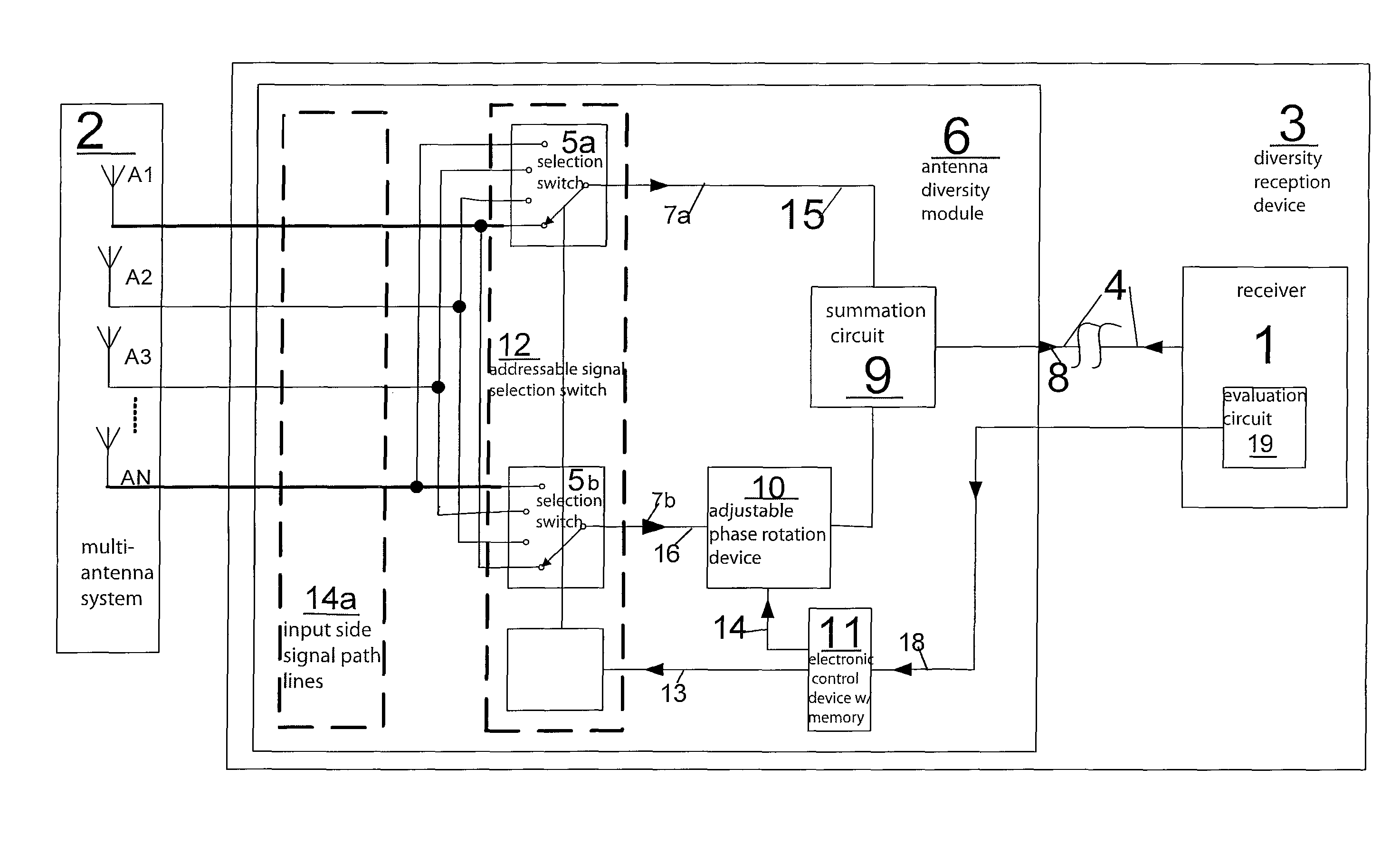
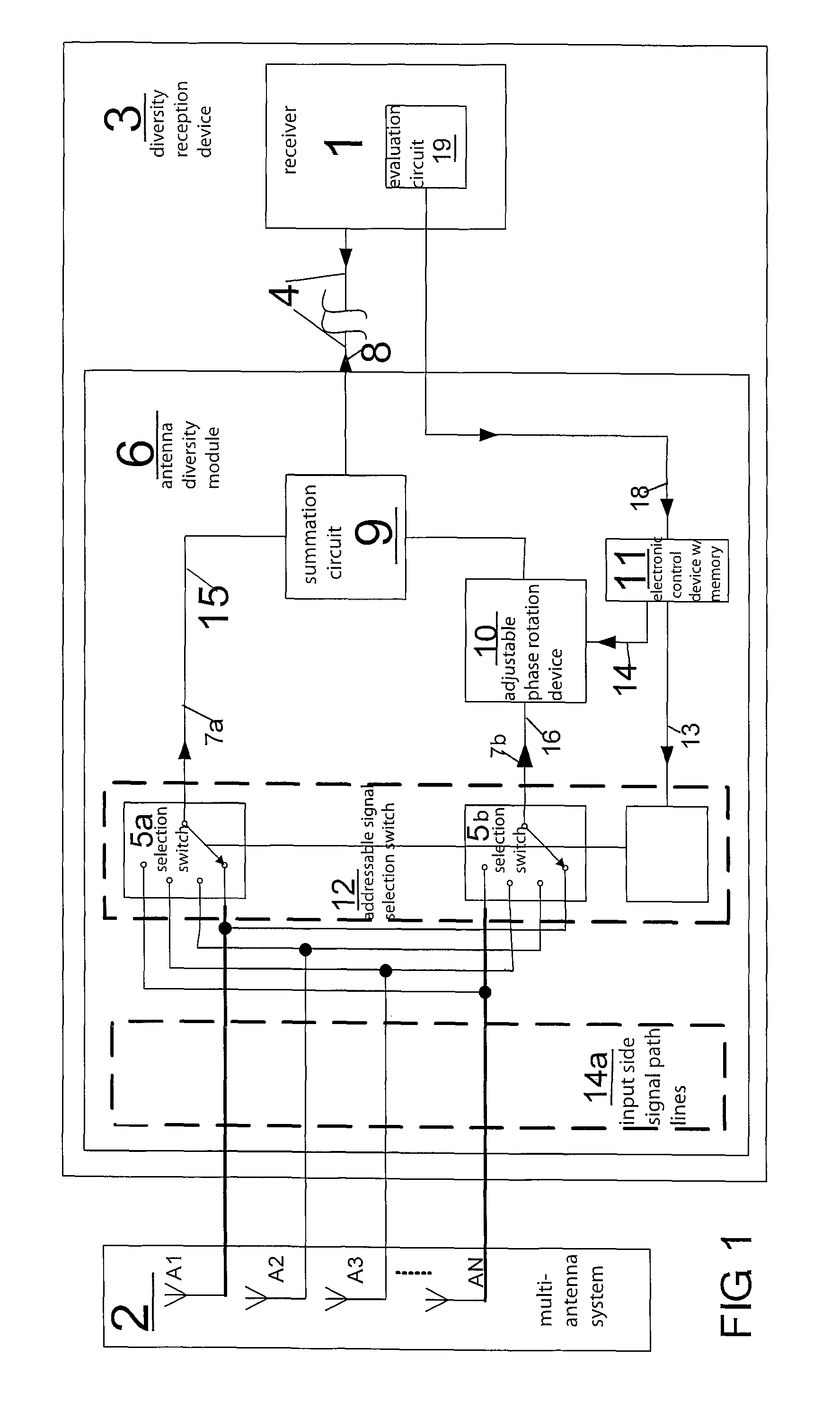
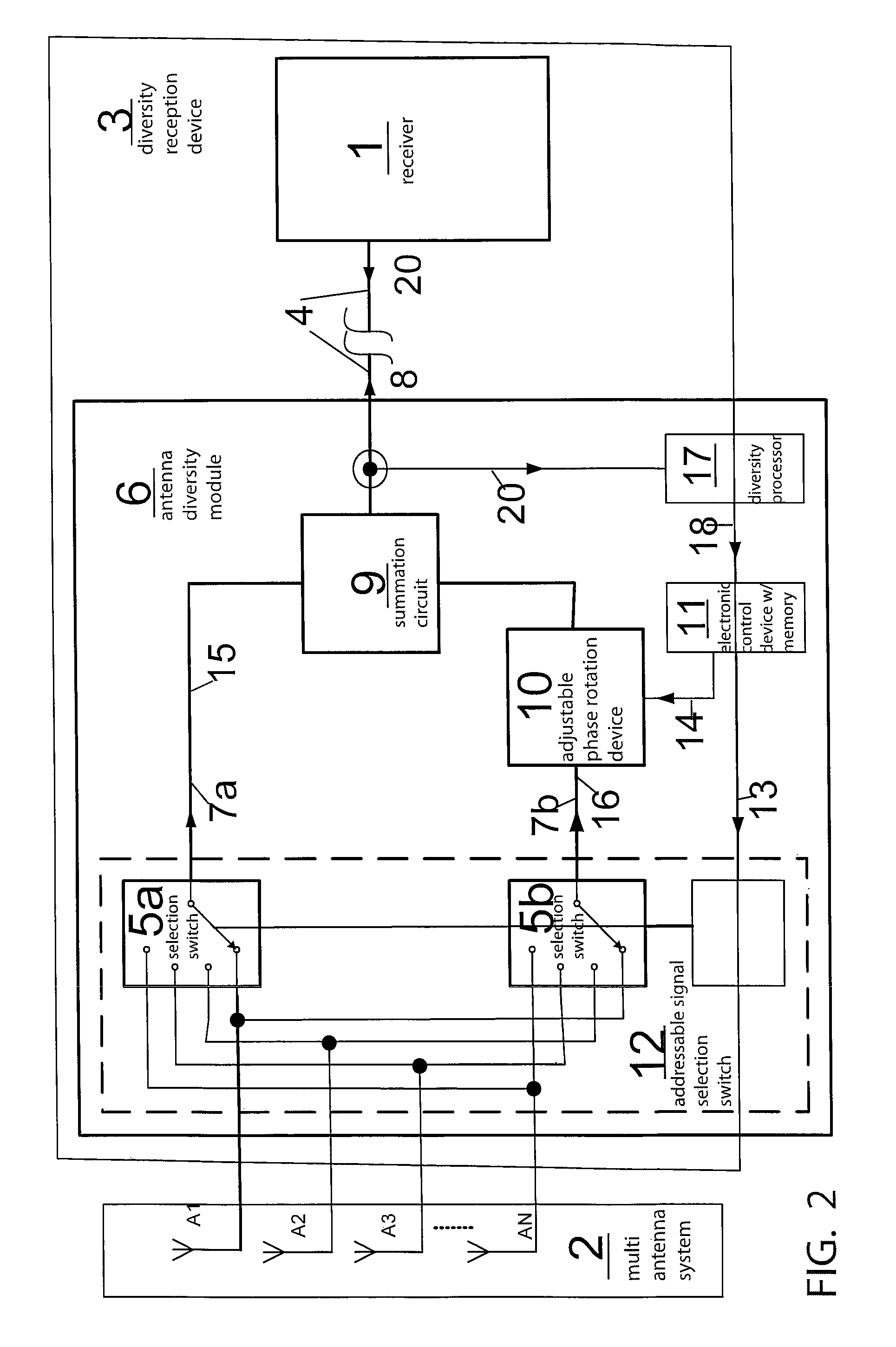
[0043]Referring in detail to the drawings, FIG. 1 shows a schematic block diagram of an antenna diversity system comprising a group of antennas or multi antenna system 2 which include a plurality of antennas Al, A2, A3, AN . . . This multi antenna system 2 is in communication with a diversity reception device 3 via a series of input side signal path lines 14a. Diversity reception device 3 includes a receiver 1, and an antenna diversity module 6 which includes an addressable signal selection switch 12 having a plurality of selection switches 5a and 5b which are controlled by a switch controller 12a.

[0044]Inside of diversity reception device 3, there is a branching of the input signal path 14a into a first separate output signal path 15 having a reception signal 7a, and a second separate output signal path 16 having a reception signal 7b. With this design, there is an adjustable phase rotation device 10 disposed along signal path 16. There is also a summation circuit 9 coupled to bot...


PUM


Abstract

An antenna diversity system for radio reception for motor vehicles, which comprises a multi-antenna system having several antennas with antenna feed lines. There can be a diversity switching device for selection of a different reception signal, and an evaluation circuit which evaluates the reception quality of the reception signal just arriving at the receiver. This evaluation circuit is designed to bring a different reception signal in terms of diversity to the receiver if interference occurs, by switching over. This design also includes at least one phase rotation device which is disposed along at least one of the signal paths.

Description

CROSS REFERENCE TO RELATED APPLICATIONS[0001]This application claims priority from German Application Serial No. 10 2005 043 304.9 filed on Sep. 12, 2005, and German Application Serial No. 10 2006 039 357.0 filed on Aug. 21, 2006 the disclosures of which are hereby incorporated herein by reference in their entirety.BACKGROUND OF THE INVENTION[0002]The invention relates to an antenna diversity system for radio reception for motor vehicles, which comprises a multi-antenna system (2) having several antennas (A1, A2, . . . AN) with antenna feed lines 2a. There can be a diversity switching device for selection of a different reception signal, and an evaluation circuit which evaluates the reception quality of the reception signal just arriving at the receiver. This evaluation circuit is designed to bring a different reception signal in terms of diversity to the receiver if interference occurs, by switching over.[0003]Antenna diversity systems having switching diversity of this type are pr...

Claims


Application Information

Patent Timeline
Patent Type & Authority Patents(United States)
IPC IPC(8): H04B7/10H04L1/02
CPCH04B7/0814H04B7/0874H04B7/084H04B7/0828H04B7/02H04B7/08
Inventor LINDENMEIER, HEINZ
Owner DELPHI DELCO ELECTRONICS EUROPE GMBH
Learn More