
Imaging arrangements and methods therefor

a technology of imaging and arrangement, applied in the field of imaging applications, can solve the problems of limiting the amount of light collected in imaging applications such as those involving cameras, video cameras, microscopes, telescopes, etc., and most imaging devices and conventional cameras such as digital still cameras and video cameras do not record most of the information abou

Active Publication Date: 2011-05-03
THE BOARD OF TRUSTEES OF THE LELAND STANFORD JUNIOR UNIV
View PDF26 Cites 184 Cited by
  • Summary
  • Abstract
  • Description
  • Claims
  • Application Information

AI Technical Summary

Problems solved by technology

Imaging applications such as those involving cameras, video cameras, microscopes, telescopes and more have generally been limited in the amount of light that is collected.
That is, most imaging devices do not record most of the information about light distribution entering the device.
For example, conventional cameras such as digital still cameras and video cameras do not record most of the information about the light distribution entering from the world.
In these devices, collected light is often not amenable to manipulation for a variety of approaches, such as for focusing at different depths (distances from the imaging device), correcting for lens aberrations or manipulating an angle of view.
For video-imaging applications, similar problems prevail, with a collection of images used in video applications failing to capture scenes in focus.
Many imaging applications suffer from aberrations with the equipment (lenses) used to collect light.
Correction for aberrations has typically involved the use of corrective optics, when tend to add bulk, expense and weight to imaging devices.
In some applications benefiting from small-scale optics, such as camera phones and security cameras, the physical limitations associated with the applications make it undesirable to include additional optics.
Difficulties associated with the above have presented challenges to imaging applications, including those involving the acquisition and altering of digital images.

Method used


Image

  • Imaging arrangements and methods therefor
  • Imaging arrangements and methods therefor
  • Imaging arrangements and methods therefor

Examples


Embodiment Construction

The present invention is believed to be useful for a variety of different types of devices, and the invention has been found to be particularly suited for electronic imaging devices and applications. While the present invention is not necessarily limited to such applications, various aspects of the invention may be appreciated through a discussion of various examples using this context.

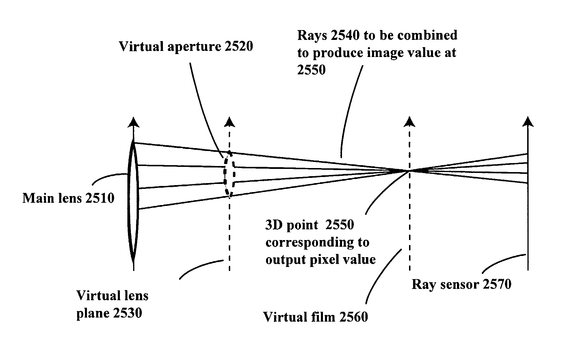
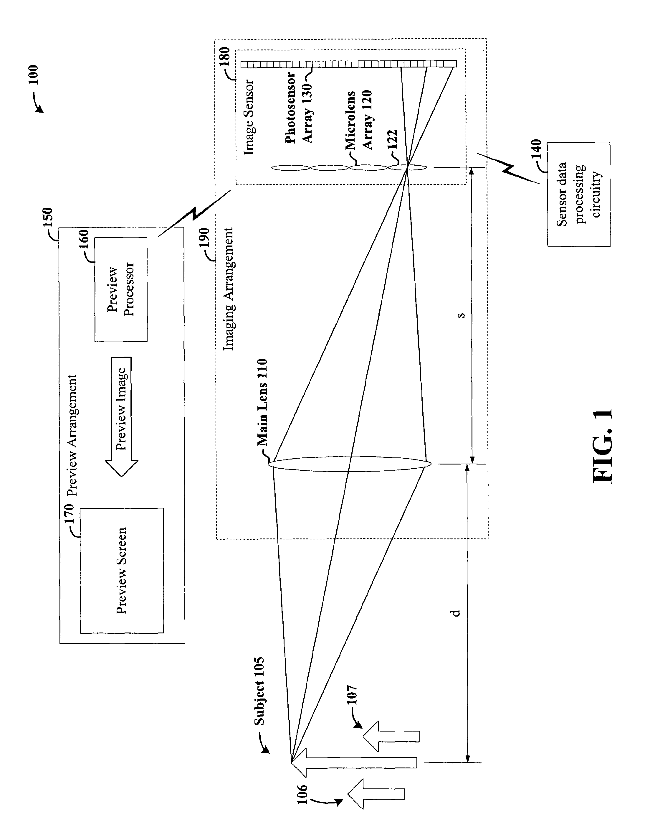
According to an example embodiment of the present invention, a four-dimensional (4D) light field (e.g., the light traveling along each ray in a region such as free space) is detected using an approach involving the determination of the amount and direction of light arriving at a sensor located at a focal plane. The two-dimensional position of light in the focal plane is detected, together with information characterizing the direction from which the light arrived at particular locations in the plane. With this approach, the directional lighting distribution arriving at different locations on the sensor...


PUM


Abstract

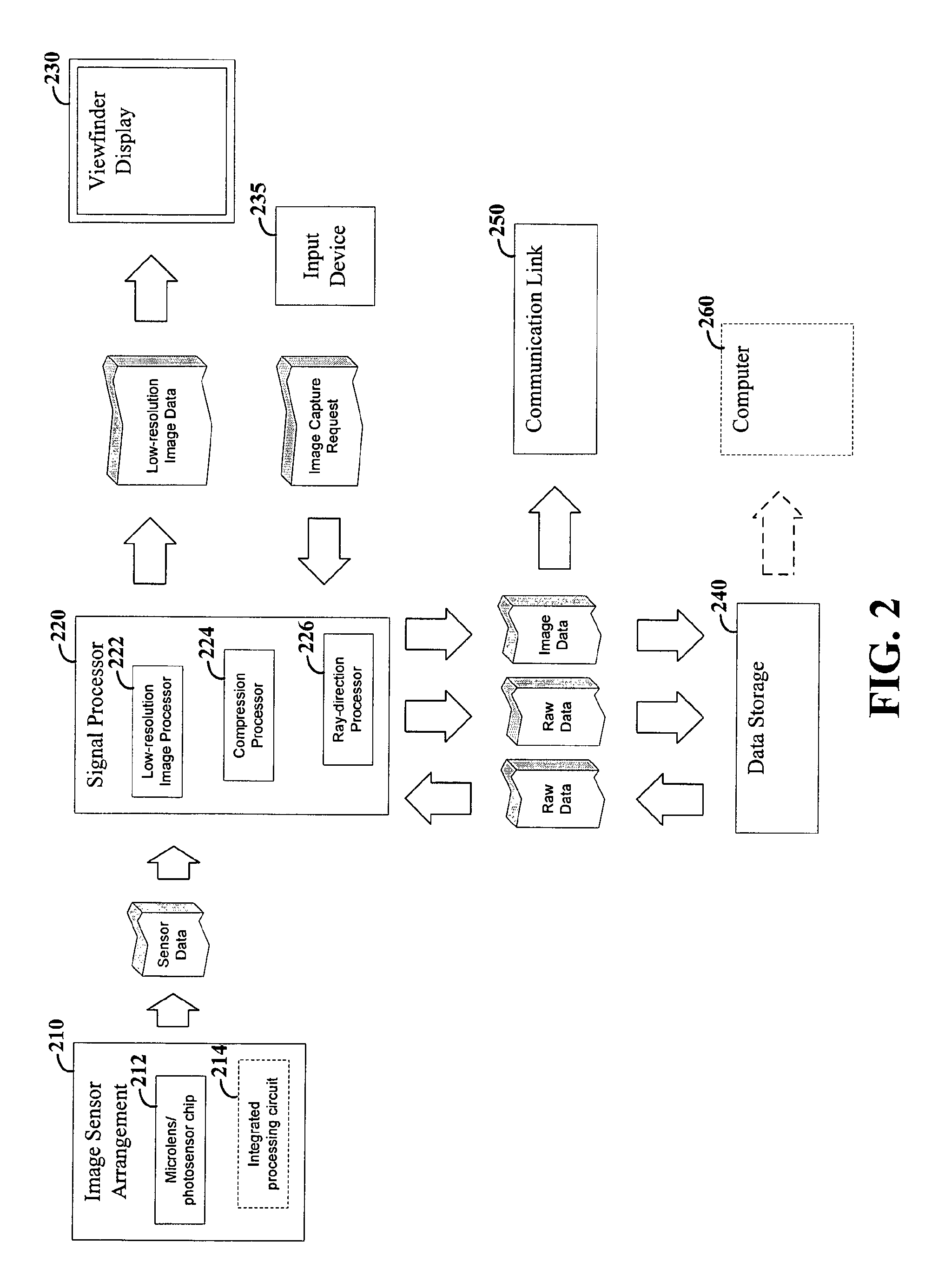
Image data is processed to facilitate focusing and / or optical correction. According to an example embodiment of the present invention, an imaging arrangement collects light data corresponding to light passing through a particular focal plane. The light data is collected using an approach that facilitates the determination of the direction from which various portions of the light incident upon a portion of the focal plane emanate from. Using this directional information in connection with value of the light as detected by photosensors, an image represented by the light is selectively focused and / or corrected.

Description

FIELD OF THE INVENTIONThe present invention relates generally to imaging applications, and more specifically to processing image data to focus and / or correct the image data.BACKGROUNDImaging applications such as those involving cameras, video cameras, microscopes, telescopes and more have generally been limited in the amount of light that is collected. That is, most imaging devices do not record most of the information about light distribution entering the device. For example, conventional cameras such as digital still cameras and video cameras do not record most of the information about the light distribution entering from the world. In these devices, collected light is often not amenable to manipulation for a variety of approaches, such as for focusing at different depths (distances from the imaging device), correcting for lens aberrations or manipulating an angle of view.For still-imaging applications, typical imaging devices capturing a particular scene generally focus upon a su...

Claims


Application Information

Patent Timeline
Patent Type & Authority Patents(United States)
IPC IPC(8): G03B13/00H04N5/232H04N23/75
CPCG02B27/0075H01L27/14627H04N13/0235H04N5/23232H04N5/23293H04N5/2173H04N5/23212G02B3/0056H04N13/236H04N23/951H04N25/611H04N25/61H04N25/60
Inventor NG, YI-RENHANRAHAN, PATRICK M.LEVOY, MARC S.HOROWITZ, MARK A.
Owner THE BOARD OF TRUSTEES OF THE LELAND STANFORD JUNIOR UNIV
Learn More