
Electronic load device for power supply product to be tested and method for regulating bandwidth thereof

a technology of electronic load and power supply product, which is applied in the direction of speed/acceleration/shock measurement, special purpose recording/indication apparatus, instruments, etc., can solve the problems of resistors, capacitors, resistors, etc., and electronic load devices are not like real load constructed,

Active Publication Date: 2011-04-26
CHROMA ATE
View PDF8 Cites 4 Cited by
  • Summary
  • Abstract
  • Description
  • Claims
  • Application Information

AI Technical Summary

Problems solved by technology

It is due to the fact that the real load constructed by the resistors, inductors and capacitors are usually not easy to be changed due to some reasons such as the component adjustment are rather poor and difficulty to be carried out but unfortunately it is usually a necessary process.
However, the electronic loading device is not like the real load constructed by the purely passive components such as resistor(s), inductor(s) and capacitor(s).
Hence, the response time is incompatible with the real load.
Aside from that, the output impendence of the OT may affect the working bandwidth range.
Since the electronic loading device according to prior art are usually found to have a finite but a fixed bandwidth range that is the main reason why a testing engineer who is not familiar to the output of OT but performs a test with high current may cause the testing system encountered malfunctions, or even causes the OT or the electronic loading device to be burned down due to abnormal oscillation.
Consequently, the applied field of the electronic load device is highly restricted.

Method used


Image

  • Electronic load device for power supply product to be tested and method for regulating bandwidth thereof
  • Electronic load device for power supply product to be tested and method for regulating bandwidth thereof

Examples


Embodiment Construction

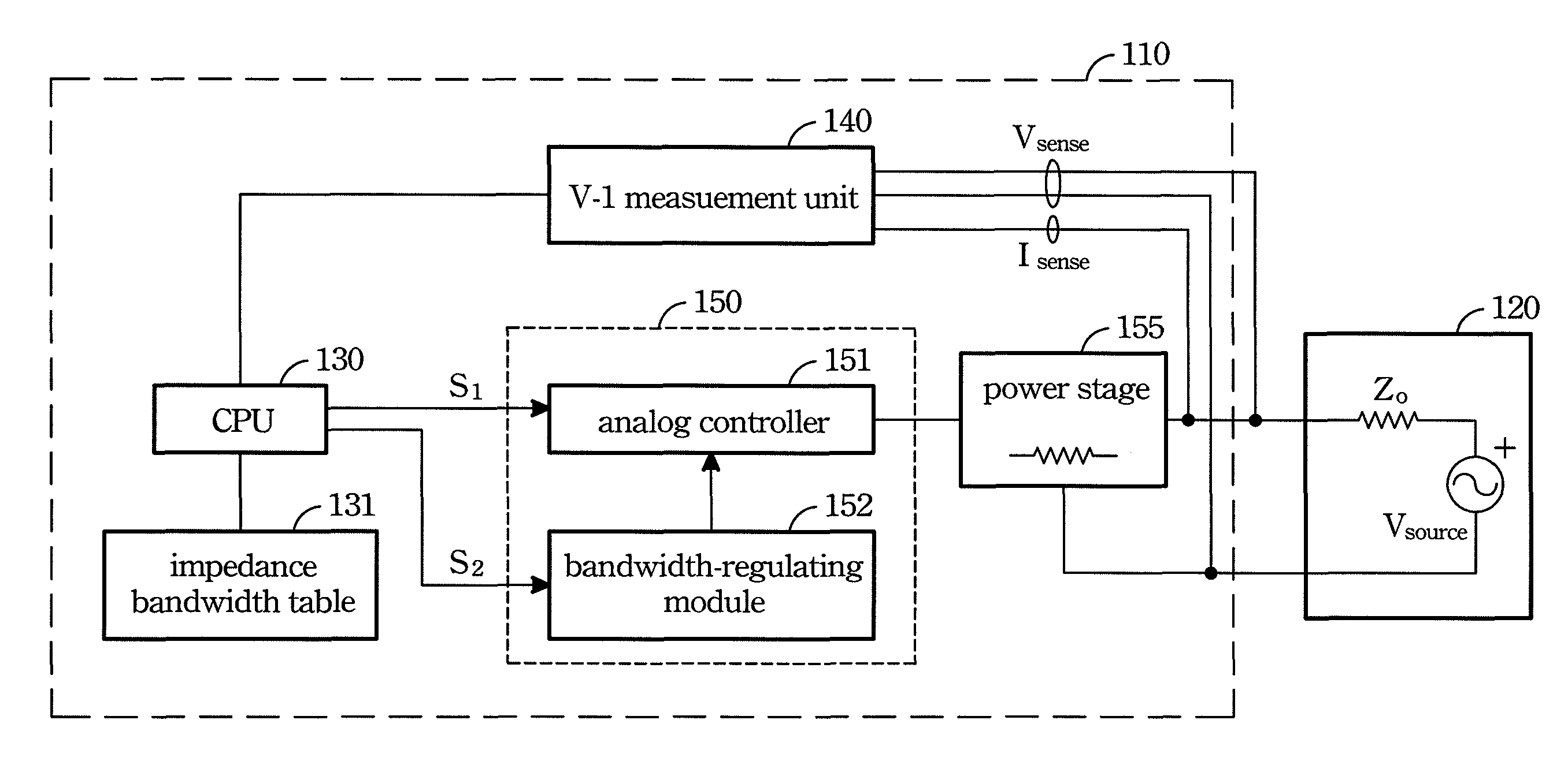
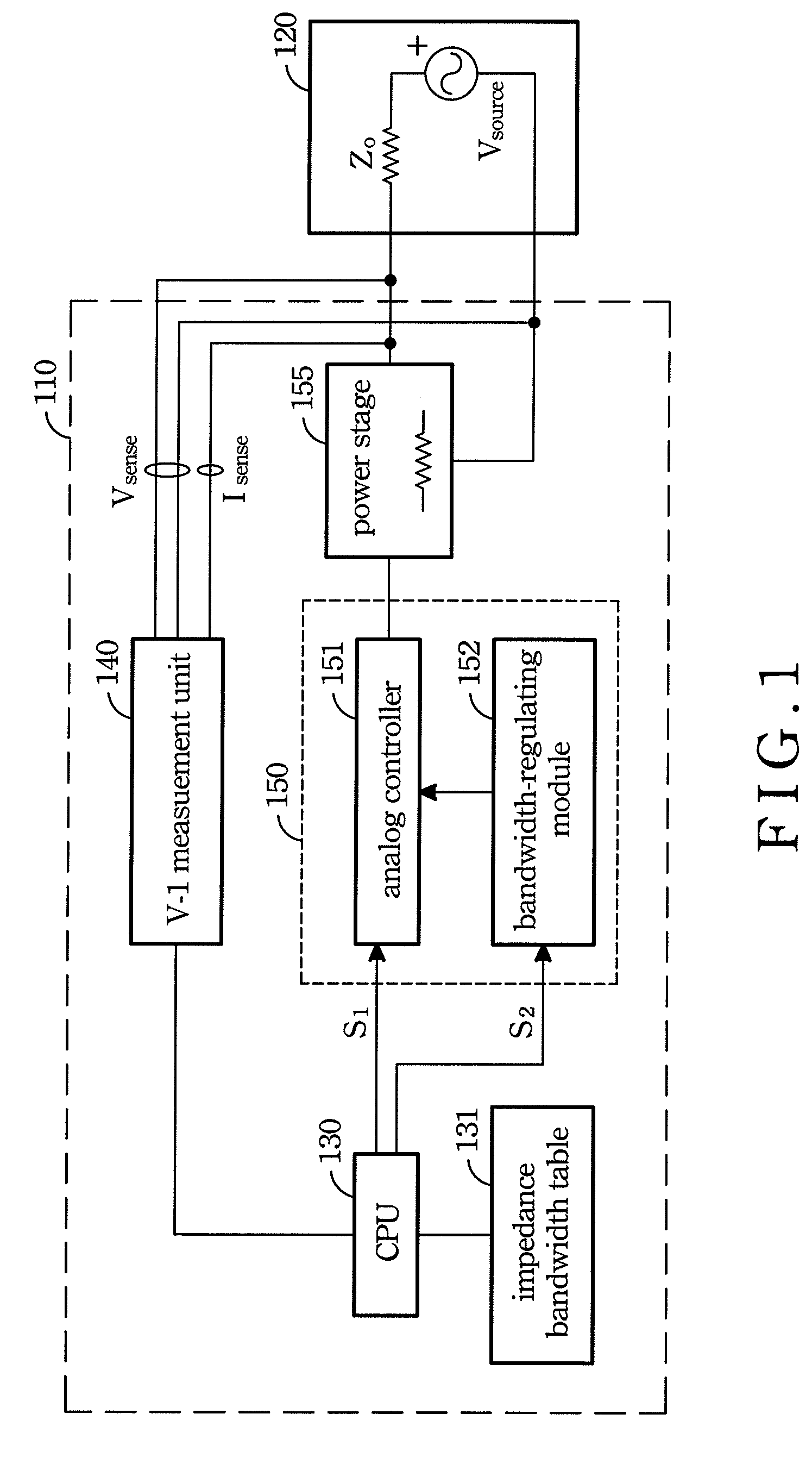
[0012]As forgoing description in the background of the invention, the AC power supply products in the current market have a variety of output characteristics and can not be summarized as an universal type. As the knowledge of the author, the main stream of impedance of the power supply is inductance type. The distribution range of the inductance of the power supply is found from a several of μH to mH (Henry). Therefore, to perform an active operation in such border range to test an OT by using the electronic load, it should have an electronic loading device whose bandwidth is adjustable according to output impedance inherited.

[0013]The present invention is to develop such an electronic loading device. Accordingly, a mapping table having relationships between the bandwidth versus output impedance is built up firstly. The mapping table hereinafter called impedance-bandwidth table. That is the output impedance of OT will be measured before it is to be tested. And then the bandwidth of ...


PUM


Abstract

An electronic load device provided for testing an OT (power supply to be tested) and the working bandwidth is regulated and set according to the output impedance of the OT. The electronic load device comprises a CPU, an impedance-bandwidth table, a voltage-current measurement unit, a power stage and a control module. Firstly, a current pulled out from the OT to the power stage is called by the CPU. Thereafter, an output impedance of the OT is measured by the voltage-current measurement unit and analysis by the CPU. Next, a working bandwidth of the electronic load device is regulated and set by the control module according to the output impedance and the impedance-bandwidth table.

Description

BACKGROUND OF THE INVENTION[0001]1. Field of the Invention[0002]The present invention relates to an electronic load device, and more particularly to an electronic load device is capable of regulating a working bandwidth regulated for a power supply product to be tested.[0003]2. Description of the Prior Art[0004]In the power supply industry, when developing a power source such as power supply or UPS uninterrupted power source product (hereinafter called objected to be tested and abbreviated as OT), an electronic loading is usually provided for tests. It is due to the fact that the real load constructed by the resistors, inductors and capacitors are usually not easy to be changed due to some reasons such as the component adjustment are rather poor and difficulty to be carried out but unfortunately it is usually a necessary process.[0005]However, the electronic loading device is not like the real load constructed by the purely passive components such as resistor(s), inductor(s) and cap...

Claims


Application Information

Patent Timeline
Patent Type & Authority Patents(United States)
IPC IPC(8): G06F19/00
CPCG01R31/31721G01R31/3004
Inventor KAO, HUNG-HSIANGCHEN, WEN-CHUNGLIU, KUO-CHENGTSOU, MING-YING
Owner CHROMA ATE
Learn More