
System and method using magnetic anomaly field magnitudes for detection, localization, classification and tracking of magnetic objects

a magnetic anomaly and magnitude technology, applied in the field of magnetic sensing systems, can solve the problems of limited effective range of current magnetic anomaly sensing-based systems, reduced magnetic field strength, and inability to produce a practical long-range dlc and/or tracking system, etc., to achieve the effect of improving the detection, classification and/or tracking rang

Inactive Publication Date: 2011-04-26
USA AS REPRESENTED BY THE SEC OF THE NAVY THE
View PDF2 Cites 102 Cited by
  • Summary
  • Abstract
  • Description
  • Claims
  • Application Information

AI Technical Summary

Benefits of technology

[0010]Accordingly, it is an object of the present invention to provide a passive magnetic anomaly sensing system and method having improved detection, classification and / or tracking range as compared to magnetic gradiometer based systems.
[0011]Another object of the present invention is to provide a longer-range magnetic anomaly sensing system that uses a simple sensor package.

Problems solved by technology

However, the physical nature of magnetic anomaly fields (i.e., a rapid reduction in magnetic field strength with distance) has limited the effective range of current magnetic anomaly sensing-based systems.
However, because of the limitations of conventional prior art approaches with regard to their sensing system embodiments and signal processing methods, they have not produced a practical long-range DLC and / or tracking system.
While these multiple-TM arrays enhance the effectiveness of a STAR-type gradiometer, they also increase the physical size, complexity and cost of the technology and detract from its practical usage.

Method used


Image

  • System and method using magnetic anomaly field magnitudes for detection, localization, classification and tracking of magnetic objects
  • System and method using magnetic anomaly field magnitudes for detection, localization, classification and tracking of magnetic objects
  • System and method using magnetic anomaly field magnitudes for detection, localization, classification and tracking of magnetic objects

Examples


Embodiment Construction

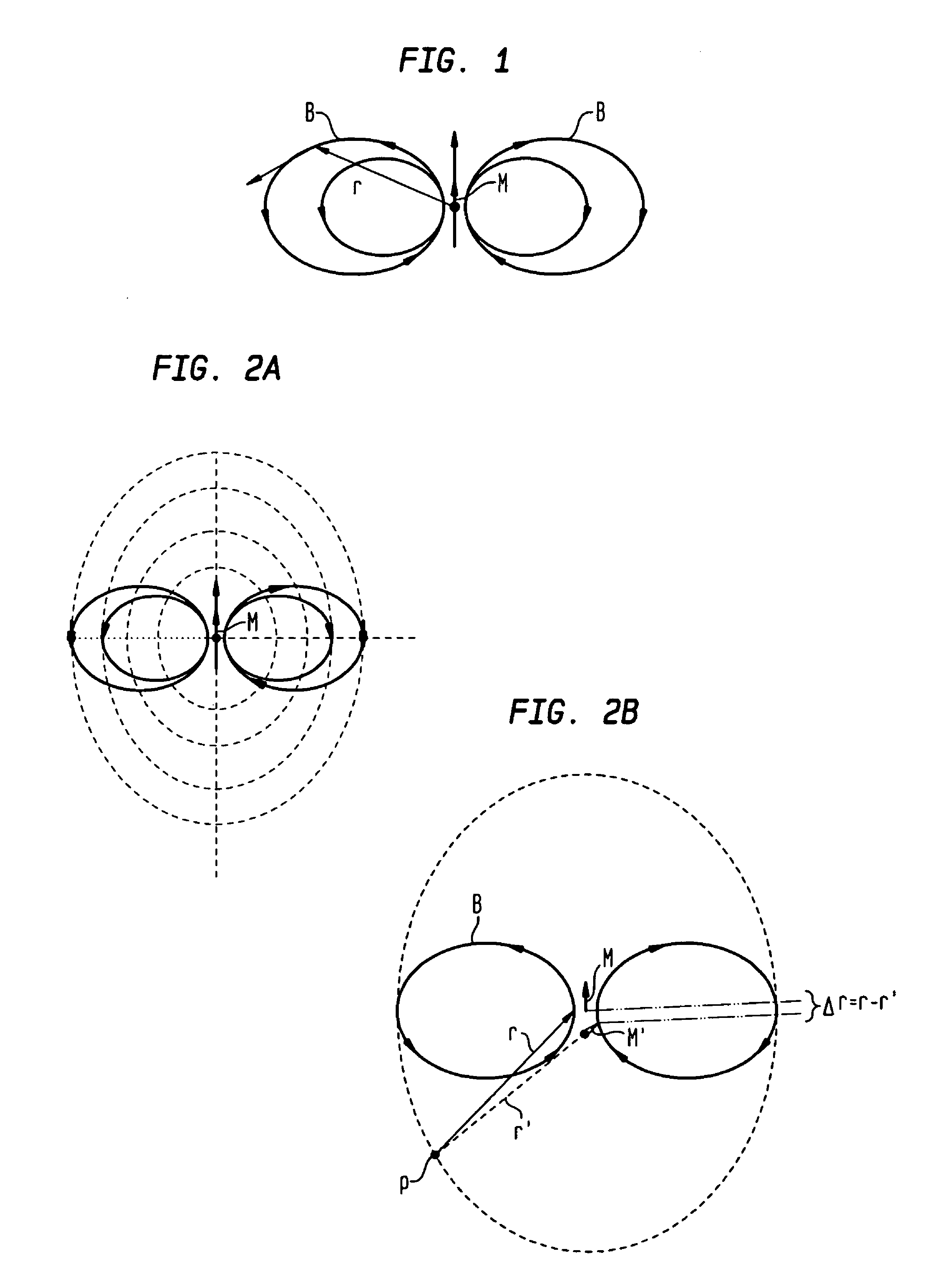
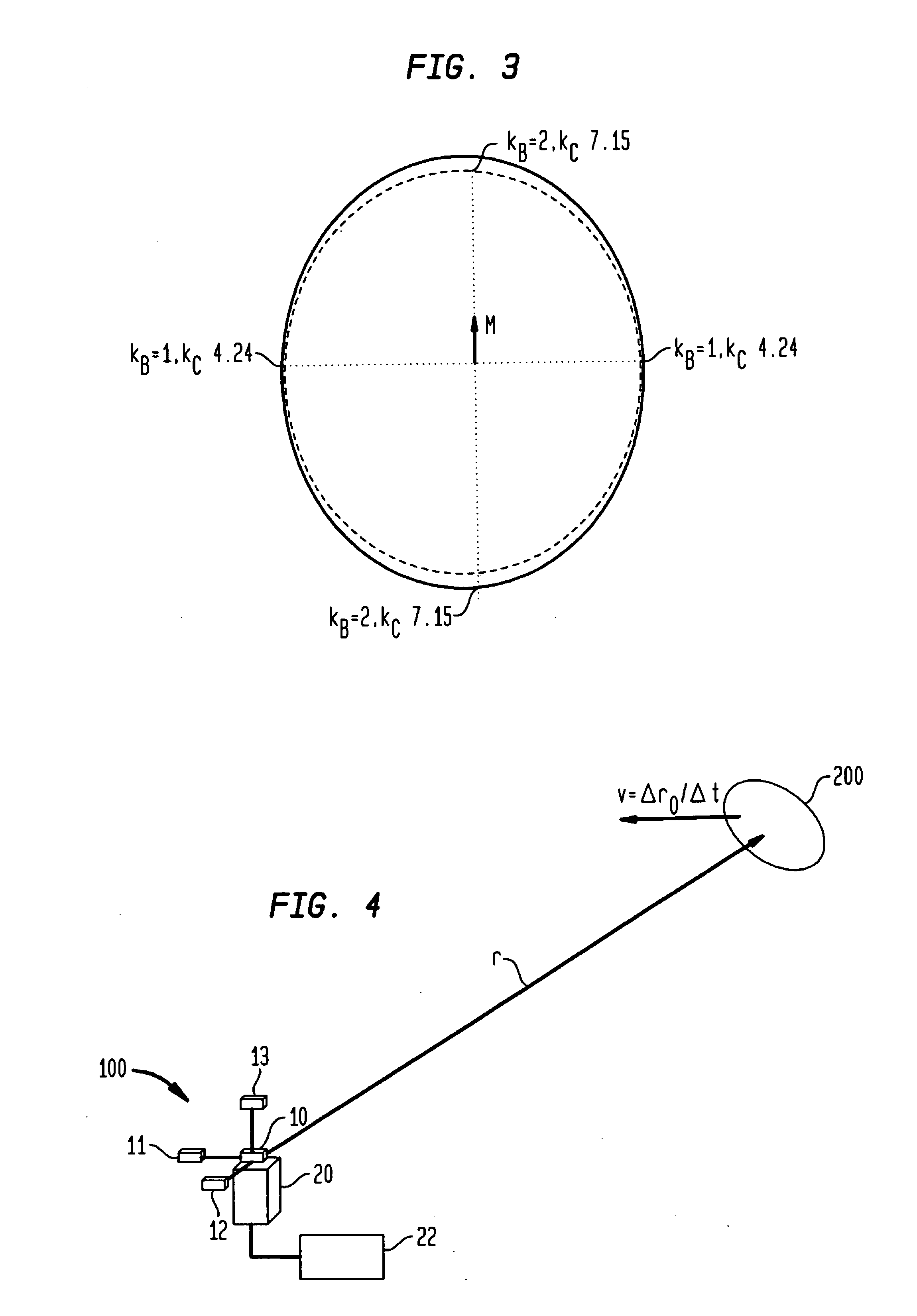
[0033]Prior to describing the present invention's novel magnetic target detection using the magnitudes of a magnetic anomaly field, some technical background related to magnetic anomaly sensing will be provided below. In general, the design and operation of magnetic sensing systems for “detection, localization and classification” (DLC) of magnetically polarized objects use the following phenomena:[0034]1. The vector magnetic fields (B) that emanate from a magnetic object's magnetic moment (i.e., magnetic signature (M)) produce relatively small, short-range “magnetic anomalies” within the Earth's magnetic background field (BE). In principle, magnetic anomaly sensing systems can measure and process B-field data to detect the presence of a magnetic target, locate its position in space, and classify the target in terms of its magnetic signature M.[0035]2. The relatively large, and locally nearly uniform (over short distances of hundreds of meters or less) magnetic induction field of Ear...


PUM


Abstract

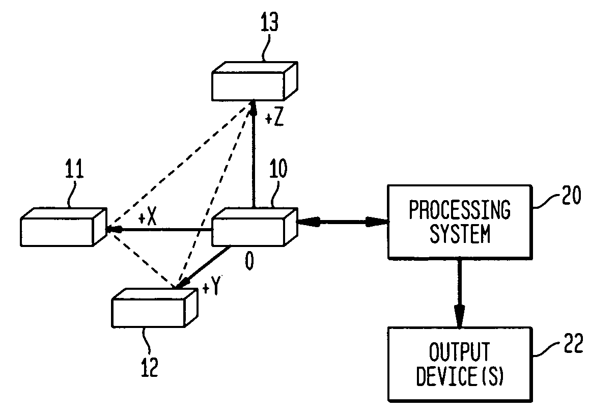
A magnetic anomaly sensing system and method uses at least four triaxial magnetometer (TM) sensors with each of the TM sensors having X,Y,Z magnetic sensing axes. The TM sensors are arranged in a three-dimensional array with respective ones of the X,Y,Z magnetic sensing axes being mutually parallel to one another. The three-dimensional array defines a geometry that forms at least one single-axis gradiometer along each of the X,Y,Z magnetic sensing axes. Information sensed by the TM sensors is to generate scalar magnitudes of a magnetic anomaly field measured at each of the TM sensors, comparisons of the scalar magnitudes to at least one threshold value, distance to a source of the magnetic anomaly field using the scalar magnitudes when the threshold value(s) is exceeded, and a magnetic dipole moment of the source using the distance.

Description

ORIGIN OF THE INVENTION[0001]The invention described herein was made in the performance of official duties by an employee of the Department of the Navy and may be manufactured, used, licensed by or for the Government for any governmental purpose without payment of any royalties thereon.FIELD OF THE INVENTION[0002]The invention relates generally to magnetic sensing systems, and more particularly to a stationary magnetic anomaly sensing system and method that uses scalar magnitudes of magnetic anomaly fields in the detection, localization, classification and / or tracking of a moving magnetic object(s).BACKGROUND OF THE INVENTION[0003]There are many potential military and commercial applications for an improved (i.e., longer-range and more economical) passive magnetic sensing system that can detect, track and measure the DC magnetic anomaly fields of moving magnetic objects or “targets” in real-time. The word “passive” indicates that the magnetic sensing system does not produce magnetic...

Claims


Application Information

Patent Timeline
IPC IPC(8): G01R33/02G01V3/08
CPCG01V3/081G01R33/022
Inventor WIEGERT, ROY
Owner USA AS REPRESENTED BY THE SEC OF THE NAVY THE
Learn More