
Structure of conductive terminal of electrical connector

Inactive Publication Date: 2011-04-26
TAIWAN SUNCAGEY INDAL
View PDF5 Cites 4 Cited by
  • Summary
  • Abstract
  • Description
  • Claims
  • Application Information

AI Technical Summary

Benefits of technology

In view of the above discussed problems, the present invention provides a novel structure of conductive terminals for an electrical connection, which is of a structure that is simple and cost saving.
Thus, the primary objective of the present invention is to provide a conductive terminal of an electrical connector that has a structure that is simple and cost saving.
The fixing arm of the conductive terminal according to the present invention forms an engaging portion that is electrically engageable with an electrical cable, so that when an electrical cable is inserted into a housing of an electrical connector of the present invention, the engaging portion forms an effective electrical engagement with the electrical cable. Further, the pressing member is operated in such a way that the pressing member undergoes a movement in a given direction to set the pressing member in the clamped condition whereby the electrical connection can securely clamp the electrical cable. With such an arrangement, the present invention makes the structure of electrical connector simple and also simplifies a corresponding mold and thus achieves the goals of reducing costs and providing a practical improvement.

Problems solved by technology

For example, the structure of the conductive terminal 2 of the conventional connector is very complicated, which leads to excessively high cost for manufacturing a mold for making the terminal 2.

Method used


Image

  • Structure of conductive terminal of electrical connector
  • Structure of conductive terminal of electrical connector
  • Structure of conductive terminal of electrical connector

Examples


Embodiment Construction

The following descriptions are exemplary embodiments only, and are not intended to limit the scope, applicability or configuration of the invention in any way. Rather, the following description provides a convenient illustration for implementing exemplary embodiments of the invention. Various changes to the described embodiments may be made in the function and arrangement of the elements described without departing from the scope of the invention as set forth in the appended claims.

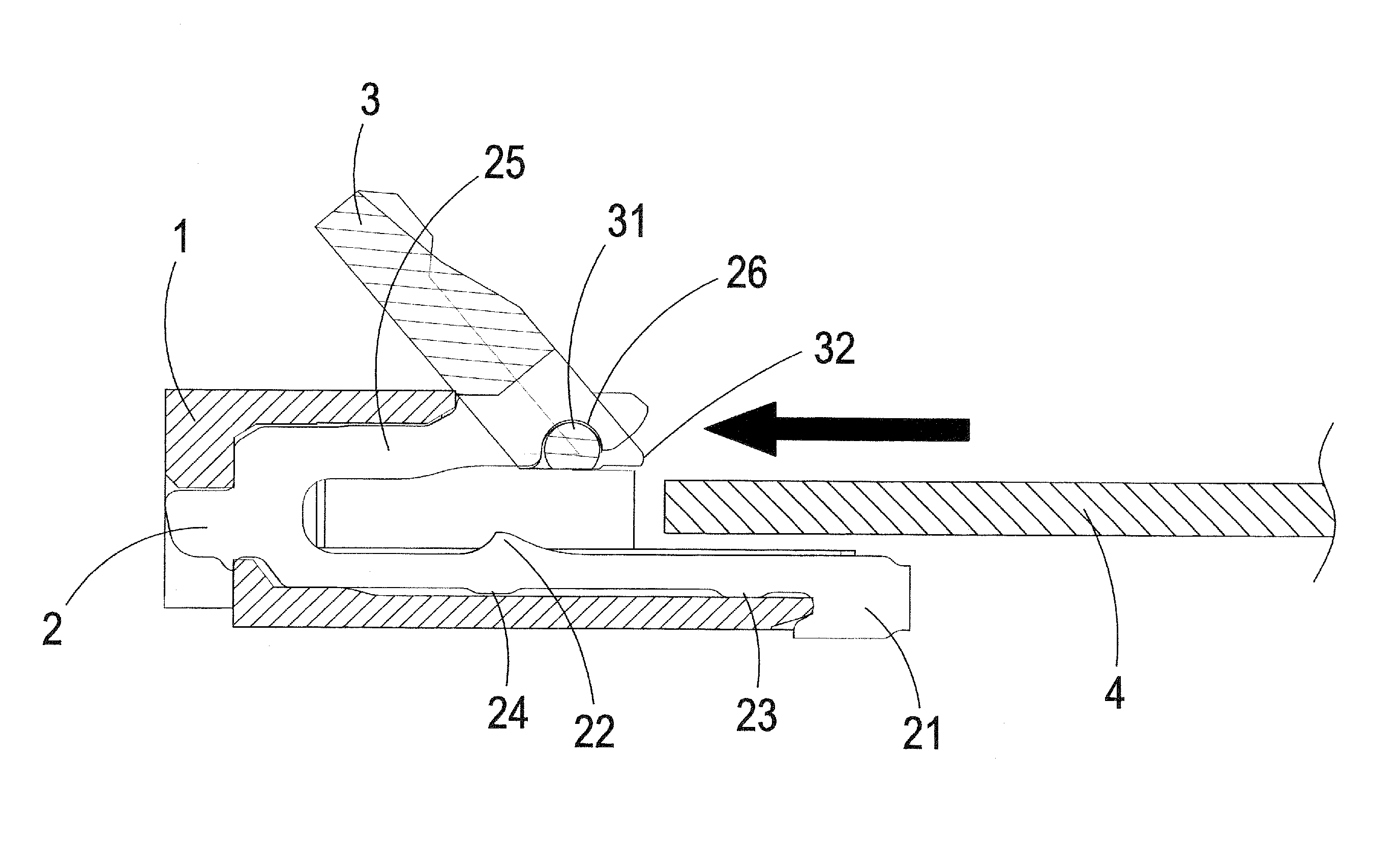
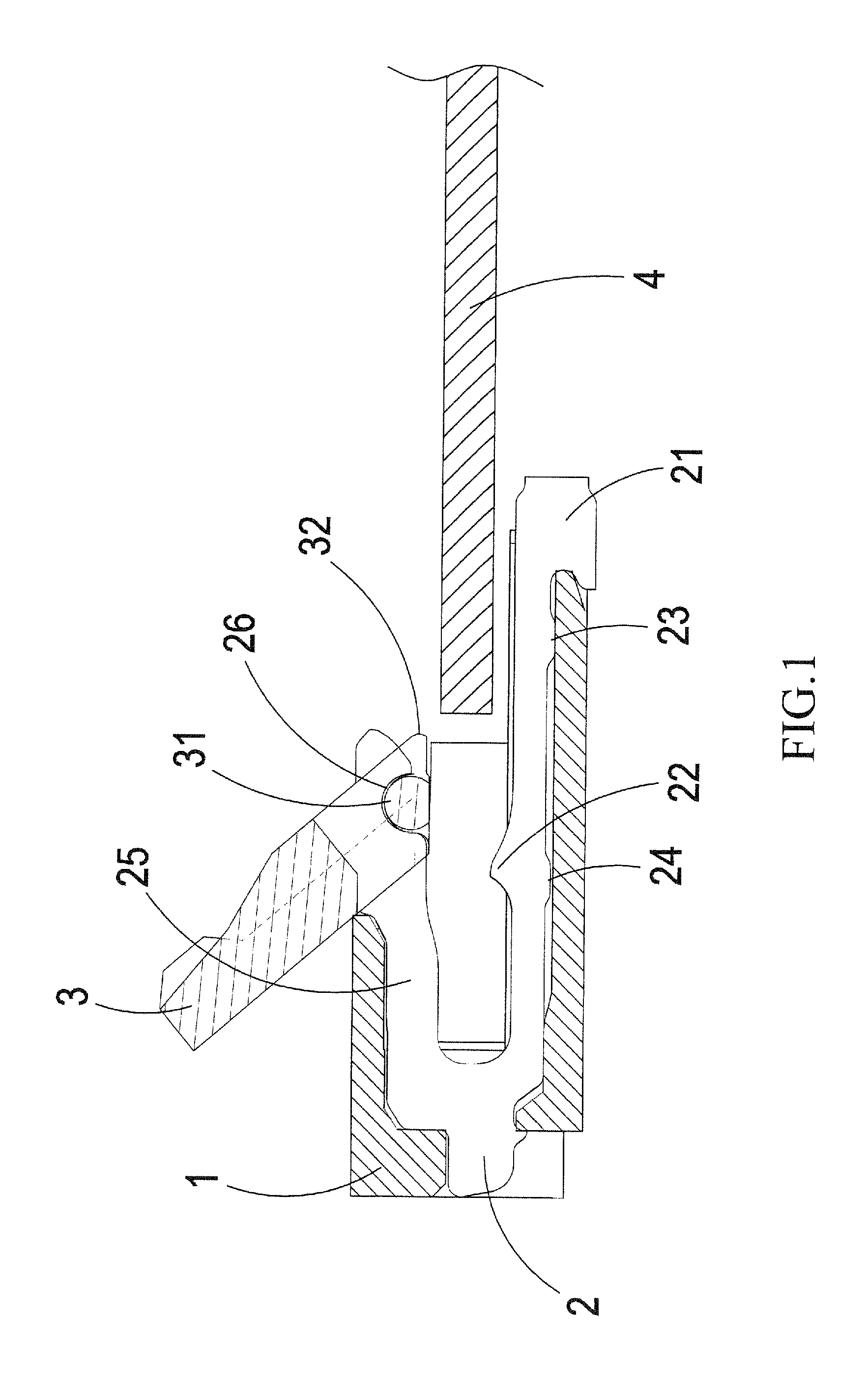
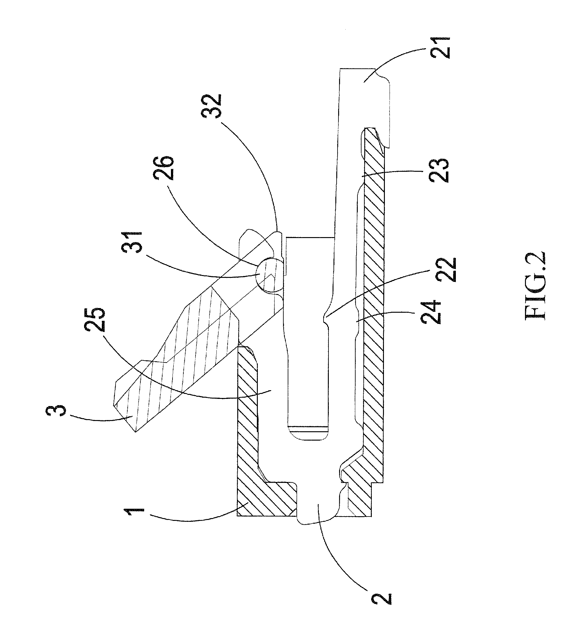
Referring to FIG. 1, which shows a cross-sectional view of a preferred embodiment according to the present invention, the present invention comprises the following constituent components:

a housing 1;

a conductive terminal 2, which is received and fixed in the housing 1, the conductive terminal 2 comprising a fixing arm 21 and a depressed arm 25 extending in the same direction and substantially parallel to each other, wherein the depressed arm 25 has an end forming a depressed portion 26 and the fixing arm ...


PUM


Abstract

An electrical connector includes a housing, a conductive terminal, and a pressing member. The conductive terminal is received and fixed in the housing. The conductive terminal includes a fixing arm and a depressed arm extending in the same direction and substantially parallel to each other. The depressed arm has an end forming a depressed portion. The fixing arm is fixed with respect to the housing. The fixing arm has a side forming an engaging portion for electrically engaging an electrical cable and an opposite side forming at least one abutment portion positioned against an inner wall of the housing. The pressing member includes a pivot, which is extended in a given direction to form a depressing portion that is operable to depress the depressed arm. The pressing member is movable to switch between an open condition and a clamped condition.

Description

TECHNICAL FIELD OF THE INVENTIONThe present invention generally relates to a conductive terminal of an electrical connector, and more particularly to a conductive terminal of an electrical connector that has a structure that is simple and cost-saving.DESCRIPTION OF THE PRIOR ARTTo ensure a desired electrical connection with a flexible circuit board, such a flexible circuit board is often coupled to an electrical connector. An electrical connector of such a purpose is often composed of a housing, conductive terminals, and a pressing member. When the pressing member of the electrical connector is operated, the pressing member acts upon the conductive terminals to have the terminals depressed against the flexible circuit board.As shown in FIG. 6, which schematically illustrates a conventional electrical connector, the conventional connector comprises a housing 1, conductive terminals 2, and a pressing member 3. Each of the conductive terminals 2 is received and fixed inside the housing...

Claims


Application Information

Patent Timeline
CPCH01R12/88H01R12/79
Inventor CHEN, YEN-LIN
Owner TAIWAN SUNCAGEY INDAL
Learn More