
Network device fixture

a network device and fixture technology, applied in the field of network device fixtures, can solve the problems of affecting the heat dissipation efficiency of the network device, the limited the inability to meet the specific requirements of the company, so as to improve the flexibility of the network device and the rack, enhance the convenience and the stability of the installation, and hinder the heat dissipation effect of the network devi

Active Publication Date: 2011-04-19
ALPHA NETWORKS INC
View PDF5 Cites 13 Cited by
  • Summary
  • Abstract
  • Description
  • Claims
  • Application Information

AI Technical Summary

Benefits of technology

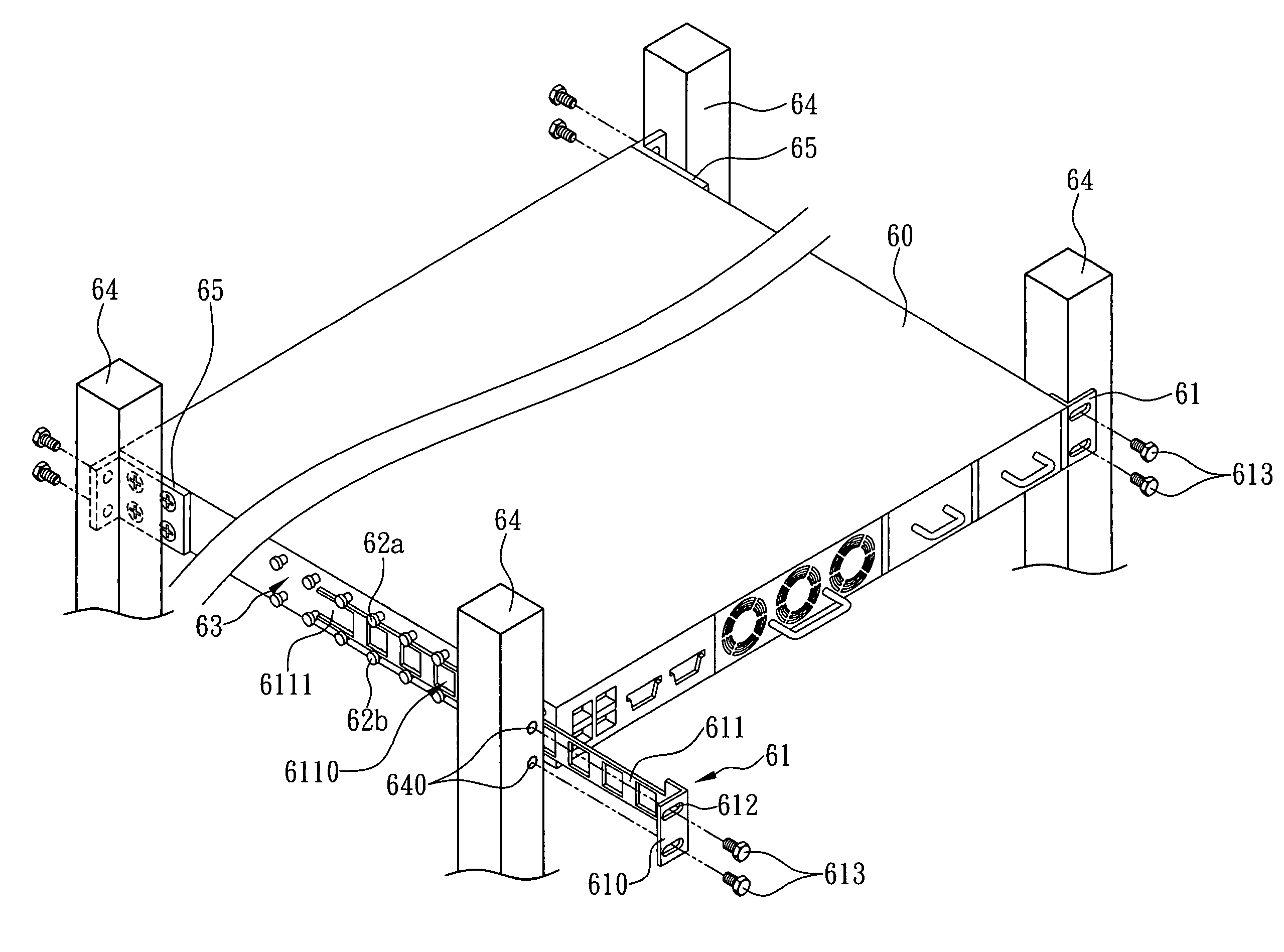
The present invention provides a network device fixture that overcomes the shortcomings of the prior art. The fixture includes a network device and two fixing elements. The network device has slide rails on both sides, and the fixing elements have locking holes and a support portion that slides into the slide rails. This allows the network device to be securely stored in a rack without the need for additional components. The support portion of each fixing element supports the network device, and an opening prevents interference with heat dissipation. An auxiliary rail element is optionally added for additional stability. The fixture improves the flexible combination of the network device and the rack, enhances the convenience of installation, and reduces material consumption.

Problems solved by technology

Personal computers no longer meet specific requirements of companies, and thus related manufacturers have developed network devices (including firewall servers, switches and routers, etc) with professional functions to meet corporate requirements.
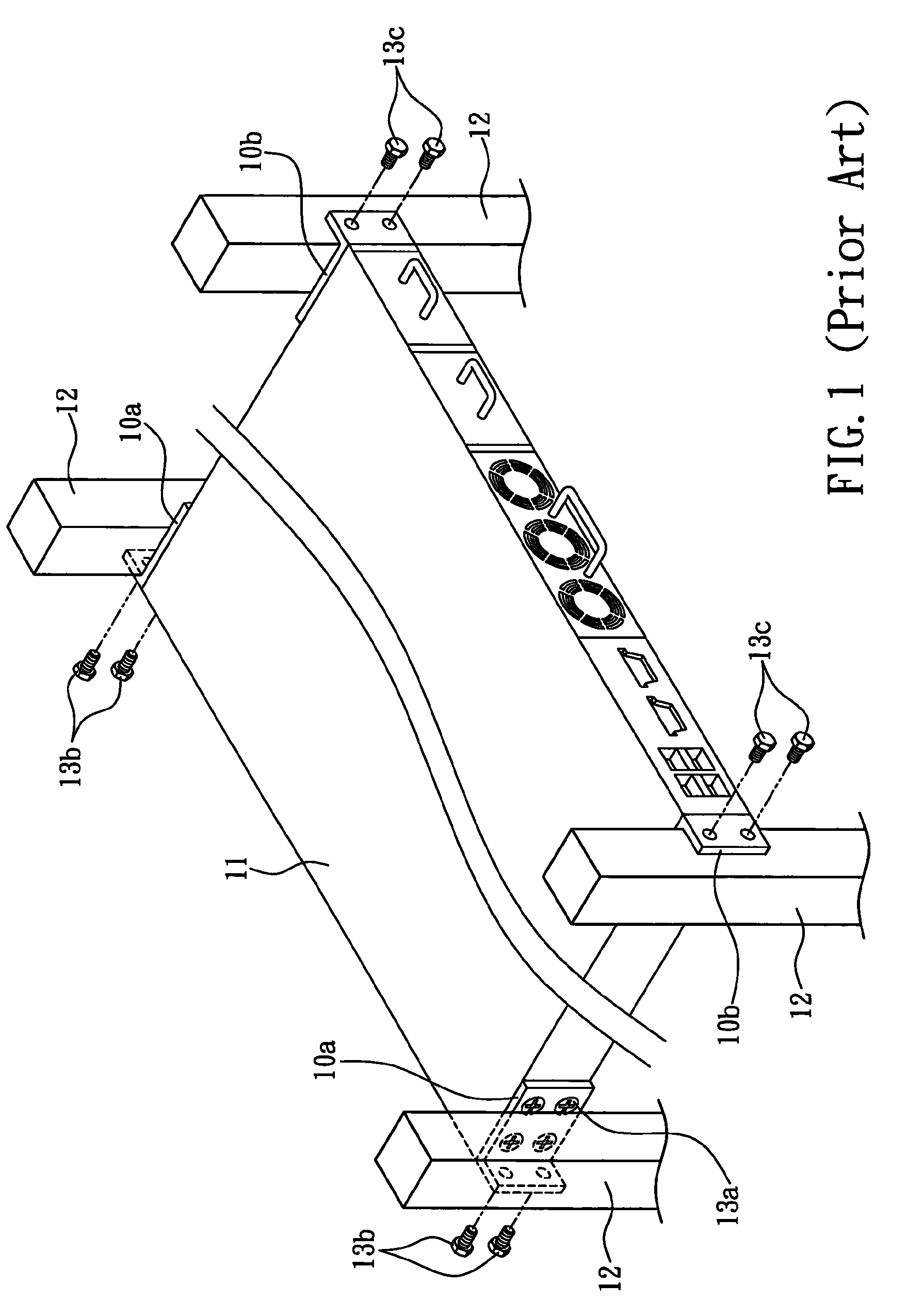
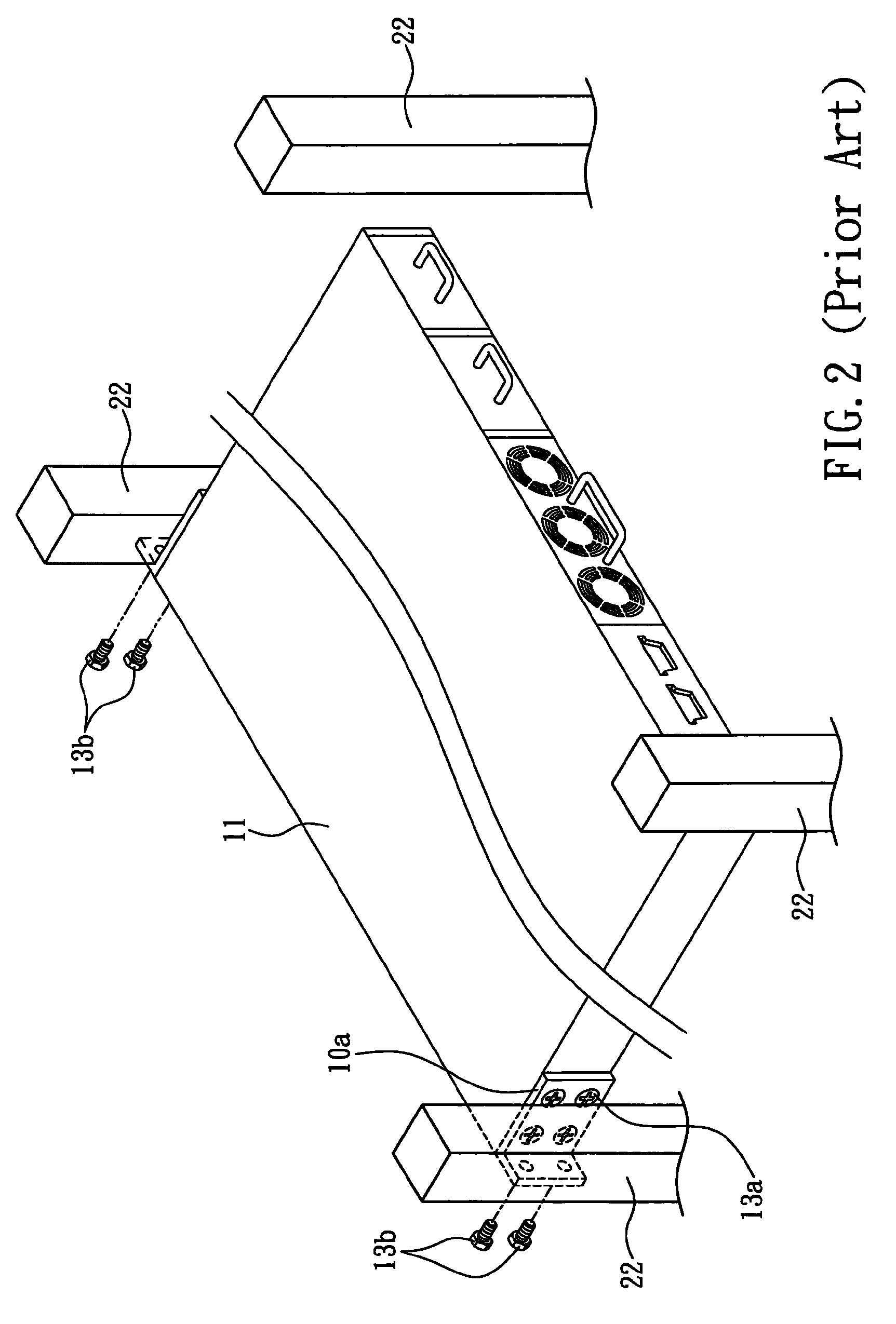
As a result, the flexible combination of the network device 11 and the rack 22 will be limited significantly.
Obviously, the prior art not only incurs a higher production cost, but also requires a higher level of difficulty on the management of components and materials.

Method used


Image

  • Network device fixture
  • Network device fixture
  • Network device fixture

Examples


Embodiment Construction

[0019]With reference to FIGS. 3 and 4 for a network device fixture in accordance with a first preferred embodiment of the present invention, the network device fixture comprises a network device 30 and two fixing elements 31, wherein at least one rail element 32 is disposed on both sides of the network device 30 adjacent to the rear of the network device 30 to form a slide rail 33 on each side of the network device 30. In this embodiment, each rail element 32 is a roller, and the rail elements 32 form the slide rail 33 on both sides of the network device 30 respectively. Although the slide rail 33 is formed by consecutive rollers in this embodiment, the present invention is not limited to such arrangement, and manufacturers can substitute the rollers by H-shaped rivets or other components to form a slide rail 33 on both sides of the network device 30 respectively during the process of manufacturing the network device fixture. Any modification easily conceived by those ordinarily ski...


PUM


Abstract

This invention discloses a network device including at least one rail element disposed at both sides of the network device at positions adjacent to the rear of the network device respectively to form a slide rail on each side, and two fixing elements each having a locking portion and a support portion, wherein the locking portion has at least one locking hole and is coupled perpendicularly to the support portion, such that when the network device is installed in a rack and the front of the network device is fixed to the front of the rack, each support portion can be extended into each corresponding slide rail, and each locking portion can be secured to the rear of the rack through each corresponding locking hole.

Description

FIELD OF THE INVENTION[0001]The present invention relates to a network device fixture, and more particularly to a network device having at least one rail element disposed on both sides adjacent to the rear of the network device to form a slide rail on each side for receiving a fixing element slid therein, so as to secure the network device on a rack stably through the fixing elements.BACKGROUND OF THE INVENTION[0002]As information technology advances rapidly, E-Business has become a trend, in addition to the fast development of personal computers (including desktop computers and notebook computers). Personal computers no longer meet specific requirements of companies, and thus related manufacturers have developed network devices (including firewall servers, switches and routers, etc) with professional functions to meet corporate requirements.[0003]In general, a system administrator usually uses a rack for installing and accommodating the network devices to facilitate a central manag...

Claims


Application Information

Patent Timeline
Patent Type & Authority Patents(United States)
IPC IPC(8): H05K5/00H05K7/16
CPCG06F1/181
Inventor LIU, TE-WEI
Owner ALPHA NETWORKS INC
Learn More