Disc brake

a disc brake and disc technology, applied in the direction of braking elements, slack adjusters, braking members, etc., can solve the problems of inconvenient interchangeability, premature replacement of the brake pad, inability to adjust the slack, etc., and achieve the effect of affecting the safety, functionality and/or durability of the brak

Active Publication Date: 2011-04-19
MERITOR HEAVY VEHICLE BRAKING SYST (UK) LTD
View PDF20 Cites 19 Cited by
  • Summary
  • Abstract
  • Description
  • Claims
  • Application Information

AI Technical Summary

Benefits of technology

[0008]In a second aspect, first and second disc brake pads are for fitment in first and second mounting structures, respectively, of a disc brake inboard and outboard, respectively, of a brake rotor. The first pad has a different functional requirement to the second pad such that fitment of the first brake pad in the second mounting structure and / or the second brake pad in the first mounting structure would impair the safety, functionality and / or durability of the brake. To prevent or inhibit such incorrect fitting, the first brake pad includes on a peripheral face or a rear face thereof a first formation and the second brake pad includes on a peripheral face or a rear face thereof a second formation. The first and second formations are arranged such that the first and second brake pads have neither mirror symmetry nor rotational symmetry when assembled in the brake and cannot be fitted in an incorrect location or an incorrect orientation when the brake has corresponding features within the mounting structures thereof.

Problems solved by technology

However, the inventors have recognized that in some circumstances, the inboard and outboard brake pads have differing dimensions or properties, and it is not desirable that they be interchangeable.
The inboard brake pad requires a relatively thick backplate because a central loading from a piston may otherwise tend to cause the inboard brake pad to flex during its application.
The fitting of these two brake pads in the incorrect location would, at the very least, be likely to cause uneven wear on the outboard brake pad when fitted in the inboard location, and therefore require the premature replacement of the brake pad.
The first brake pad has a different functional requirement to the second brake pad such that fitment of the first brake pad in the second brake pad mounting structure and / or the second brake pad in the first brake pad mounting structure impairs the safety, functionality or durability of the brake.
The second brake pad includes a second formation different from the first formation such that it may only be successfully fitted in the second brake pad mounting mounting structure and only successfully fitted in the correct orientation with the brake fully assembled.
The first pad has a different functional requirement to the second pad such that fitment of the first brake pad in the second mounting structure and / or the second brake pad in the first mounting structure would impair the safety, functionality and / or durability of the brake.

Method used


Image

  • Disc brake
  • Disc brake
  • Disc brake

Examples


Embodiment Construction

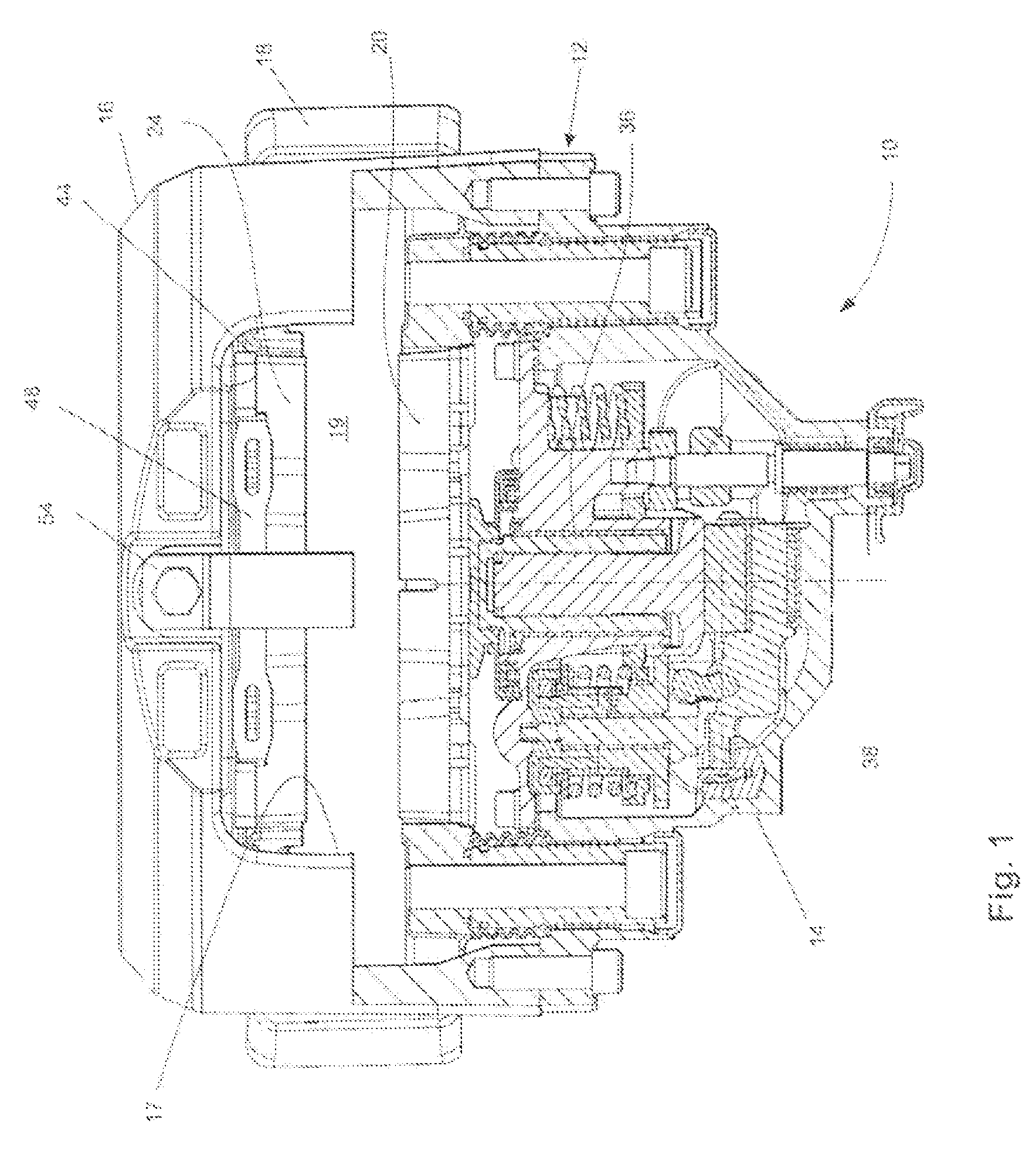
[0018]With reference to FIG. 1, a plan view of a brake is indicated generally at 10 according to one embodiment of the present invention is shown. The brake 10 includes a caliper 12 formed from a housing portion 14 and a bridge portion 16 with a radial aperture 17. When considering a vehicle upon which the brake 10 is to be mounted, the housing portion 14 is located inboard and the bridge portion 16 outboard with respect to the vehicle. The caliper 12 is slidably mounted for movement in an inboard / outboard direction with respect to a carrier 18. The carrier 18 is mounted to a fixed location with respect to a vehicle axle or steering knuckle (not shown) and is arranged to receive a brake disc or rotor (not shown) in the space 19.

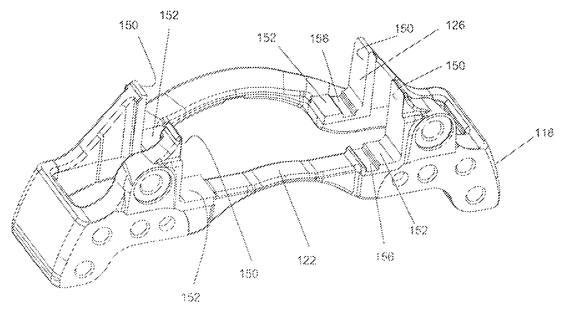
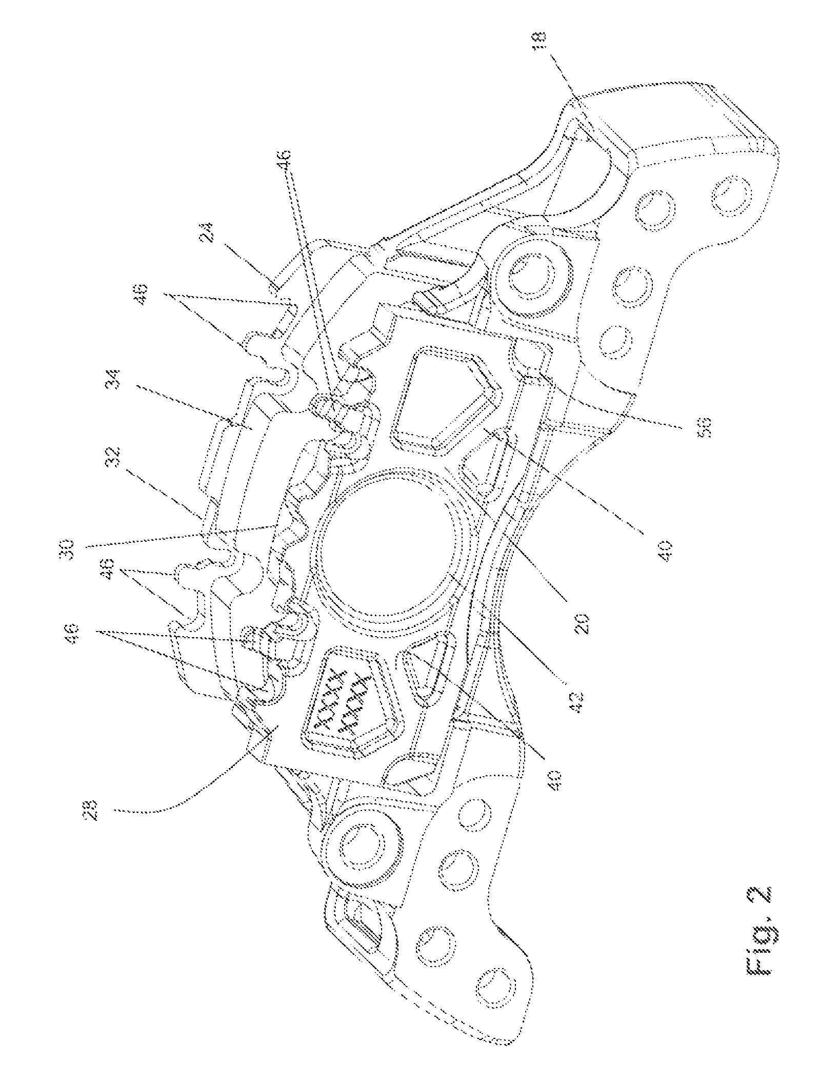
[0019]With reference to FIGS. 2 and 3, an inboard brake pad 20 is located within a first pad mounting structure in the form of an inboard opening 22 of the carrier 18 that is arranged to support the brake pad 20 in a radially inward and circumferential (i.e.,...


PUM


Abstract

A disc brake includes an actuation mechanism, and first and second brake pad mounting structures to be located, in use, adjacent opposing inboard and outboard faces, respectively, of a brake rotor to be braked. The disc brake further includes first and second brake pads located by the first and second mounting structures, respectively, such that upon application of the actuation mechanism, the brake pads clamp the brake rotor, and brake torque is reacted by the brake pad mounting structures. The first brake pad has a different functional requirement to the second brake pad such that fitment of the first brake pad in the second brake pad mounting structure and / or the second brake pad in the first brake pad mounting structure impairs the safety, functionality or durability of the brake. To prevent or inhibit such incorrect fitting, the first brake pad includes on a peripheral face or a rear face thereof a first formation in such a location that it may only be successfully fitted in the first brake pad mounting structure and only successfully fitted in the correct orientation with the brake fully assembled. The second brake pad includes a second formation different from the first formation such that it may only be successfully fitted in the second brake pad mounting structure and only successfully fitted in the correct orientation with the brake fully assembled.

Description

REFERENCE TO RELATED APPLICATION[0001]This application claims priority to United Kingdom Patent Application No. GB 0822898.3 filed Dec. 16, 2008.BACKGROUND OF THE INVENTION[0002]The present invention relates generally to a disc brake. More particularly, the present invention relates to a disc brake incorporating an arrangement for ensuring that brake pads are always fitted in a correct orientation and correct location.[0003]EP 0 752 541 (ArvinMeritor, Inc.) discloses providing formations on a pair of brake pads and corresponding features in a brake carrier to ensure that it is not possible for a brake to be fully assembled with the brake pads orientated with a backplate thereof facing a brake disc. Incorrectly fitting the brake pads in this manner is highly undesirable since the braking effectiveness of the brake is dramatically diminished and damage to the brake pad and brake disc may occur.[0004]The two pads are completely identical and include a formation that has rotational symm...

Claims


Application Information

Patent Timeline
Patent Type & Authority Patents(United States)
IPC IPC(8): F16D65/092
CPCF16D55/226F16D55/2265F16D2055/0016F16D65/02
Inventor ROBERTS, PAULMORRIS, JASONKUMAR UDUPI, KISHANPATEEL, DARSHANKULKARNI, SANJEEV
Owner MERITOR HEAVY VEHICLE BRAKING SYST (UK) LTD
Why Eureka
Try Eureka