
Methods for coupling an energy storage system to a variable energy supply system

a technology of variable energy supply and energy storage system, applied in the field of energy storage systems, can solve the problems of power swing stability, limited wind generation amount, and generally considered a non-firm resource, and achieve the effect of reducing the amount of wind generation

Active Publication Date: 2011-04-12
GENERAL ELECTRIC CO
View PDF15 Cites 27 Cited by
  • Summary
  • Abstract
  • Description
  • Claims
  • Application Information

AI Technical Summary

Benefits of technology

"The patent describes a method for coupling an energy storage system to a variable energy supply system, which can provide consistent energy output during fluctuating energy loads. The system includes a Vanadium redox battery and a battery charge controller that is connected to the variable energy supply system. The controller directs electrical power from the variable energy supply system to the battery or a utility power grid. The technical effect of this patent is to provide a reliable and flexible power source for supplying power to a grid, especially during times of high demand or when there is no fixed energy source available."

Problems solved by technology

In areas where wind penetration may be high, coupling a large number of generators generally reduces the overall power fluctuations on a system wide basis, but may still cause power swing stability concerns.
Generally the volatile nature of wind generation output limits the amount of wind generation that can be connected to the grid without causing voltage stability problems.
As such, wind power generation is generally considered a non-firm resource for system planning purposes.
However, there are circumstances where the demand for electric power suddenly and irregularly increases.
From the perspective of an electric power utility company, the associated increase in electric power demand occasioned during such occasions may be difficult to accommodate because the electric power demand are generally short lived.
Known battery installations are used to provide electric power in emergency or power-failure circumstances, but generally can not be used to provide supplemental power during demand peaks.
However, such batteries either do not have adequate electric energy storage capacity to meet the demands of energy storage systems, or are expensive.

Method used


Image

  • Methods for coupling an energy storage system to a variable energy supply system
  • Methods for coupling an energy storage system to a variable energy supply system
  • Methods for coupling an energy storage system to a variable energy supply system

Examples


Embodiment Construction

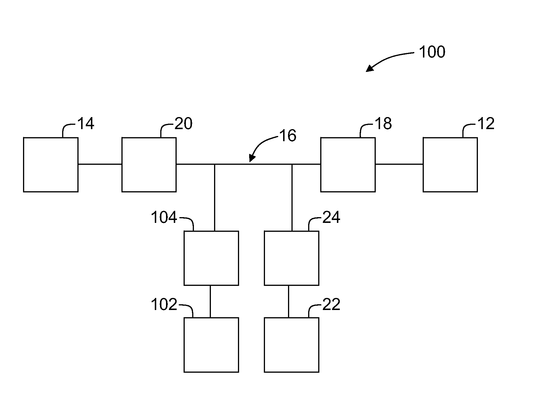
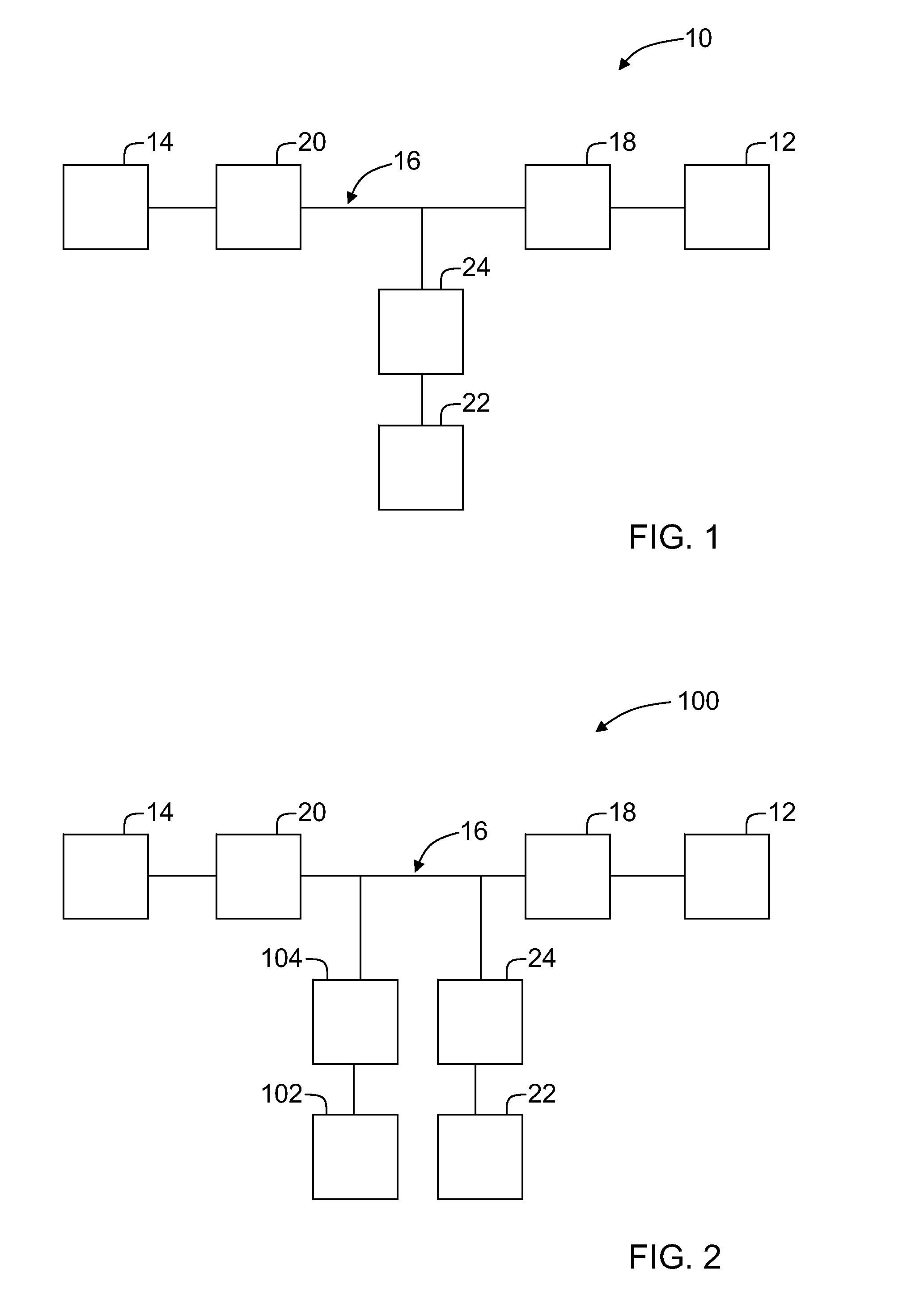
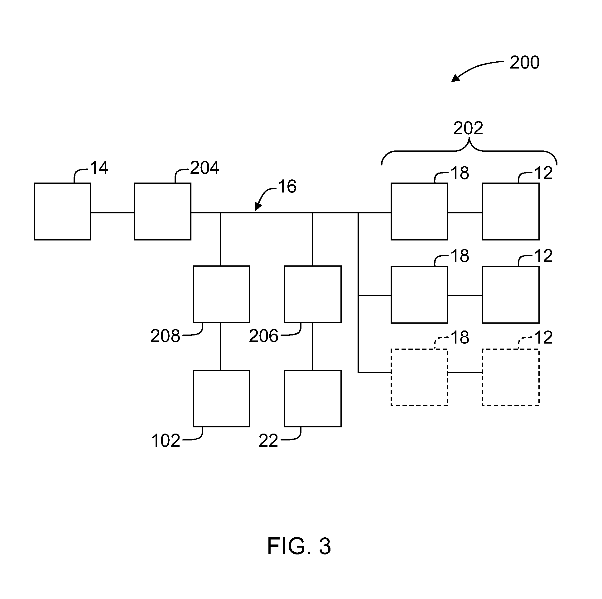
[0011]The present invention is directed to a vanadium-based reduction / oxidation (redox) regenerative energy storage system that converts chemical energy into electrical energy for use with wind generation systems. While the invention is described and illustrated in the context of a wind turbine power system, the invention is not limited to wind turbine power systems. The embodiments set forth herein are therefore exemplary only and represent various embodiments of the invention, but are not conclusive of all embodiments. As explained below, these embodiments contribute towards allowing power generating systems to store energy, as well as, provide supplemental power to an electric power grid during demand peaks or store during off-peak times.

[0012]FIG. 1 is a schematic of a wind turbine power system 10 including a wind turbine generator 12 coupled in electrical communication with a power utility grid 14. In the exemplary embodiment, wind turbine generator 12 provides power to grid 14...


PUM


Abstract

A method for coupling an energy storage system to a variable energy supply system includes providing an energy storage system including at least one Vanadium redox battery and at least one battery charge controller. The method also includes electrically coupling the at least one battery charge controller to the variable energy supply system such that the at least one battery is configured to supply a substantially consistent energy output during fluctuating energy loads of the energy supply system.

Description

BACKGROUND OF THE INVENTION[0001]This invention relates generally to energy storage systems, and more particularly, methods and apparatus for coupling an energy storage system to a variable energy supply system.[0002]At least some known wind generation systems produce a fluctuating or intermittent power output due to the variability of wind speed. When multiple generators are electrically coupled together, i.e. in arrangements known as wind farms, the fluctuation in total power output may be reduced. Under ideal conditions the variations of power output will decrease at a factor of 1 / √{square root over (n)}, where n represents the number of wind generators coupled together. In areas where wind penetration may be high, coupling a large number of generators generally reduces the overall power fluctuations on a system wide basis, but may still cause power swing stability concerns. Generally the volatile nature of wind generation output limits the amount of wind generation that can be c...

Claims


Application Information

Patent Timeline
Patent Type & Authority Patents(United States)
IPC IPC(8): H02J7/00
CPCH02J3/32H02J7/32H02J3/38H02J7/34H02J2300/28H02J3/381Y02E10/76Y02E70/30
Inventor RITTER, ALLEN MICHAELHARBOURT, CYRUS DAVIDWAGONER, ROBERT GREGORY
Owner GENERAL ELECTRIC CO
Learn More