Charged particle beam irradiator and rotary gantry

a rotary gantry and irradiator technology, applied in the field of rotary gantry irradiator and rotary gantry, can solve the problems of bigger apparatus and bigger apparatus, and achieve the effect of reducing the size of the whole apparatus, reducing the length of the irradiating port, and reducing the size of the rotary gantry

Inactive Publication Date: 2011-04-05
NAT INST OF RADIOLOGICAL SCI
View PDF26 Cites 6 Cited by
  • Summary
  • Abstract
  • Description
  • Claims
  • Application Information

AI Technical Summary

Benefits of technology

[0012]According to the present invention, the charged particle beam which enters the bending electromagnet can be scanned in the X-direction parallel to a plane including the bending trajectory of the beam and being perpendicular to the direction of the beam traveling, through controlling the bending electromagnetic field. Accordingly, the bending electromagnet can be used as an electromagnet having the same function as the irradiation field forming electromagnet which scans the beam in the X-direction, and thereby, a length of an irradiating port can be shortened because it is unnecessary to install the irradiation field electromagnet in addition to the bending electromagnet.
[0014]According to the present invention, a rotary gantry in which an irradiation field forming electromagnet which scans the beam in the X-direction is omitted can be assembled, and a length of irradiating port can be shortened. Resultantly, a rotating radius of the rotary gantry can be made smaller, and a size of the rotary gantry can be reduced.
[0015]As described above in detail, according to the present invention, the size of the whole apparatus can be reduced, because a point which is an origin of the beam being scanned can be disposed in the bending electromagnet. Because the irradiation field forming electromagnet which scans the beam in the X-direction can be omitted, the size of the whole apparatus can be reduced further, thereby.

Problems solved by technology

If a charged carbon beam (a carbon ion beam) is applied, a rather long port length around 5.5 m is needed at the shortest, and thereby, a problem that the apparatus gets bigger is raised.
If the charged particle beam irradiator as described above is applied to a rotary gantry described in patent document 1, a space needed for driving the rotary gantry should be about 18×9×9×π m3, for example, and thereby, a problem that the apparatus gets bigger is raised.

Method used


Image

  • Charged particle beam irradiator and rotary gantry
  • Charged particle beam irradiator and rotary gantry
  • Charged particle beam irradiator and rotary gantry

Examples


first embodiment

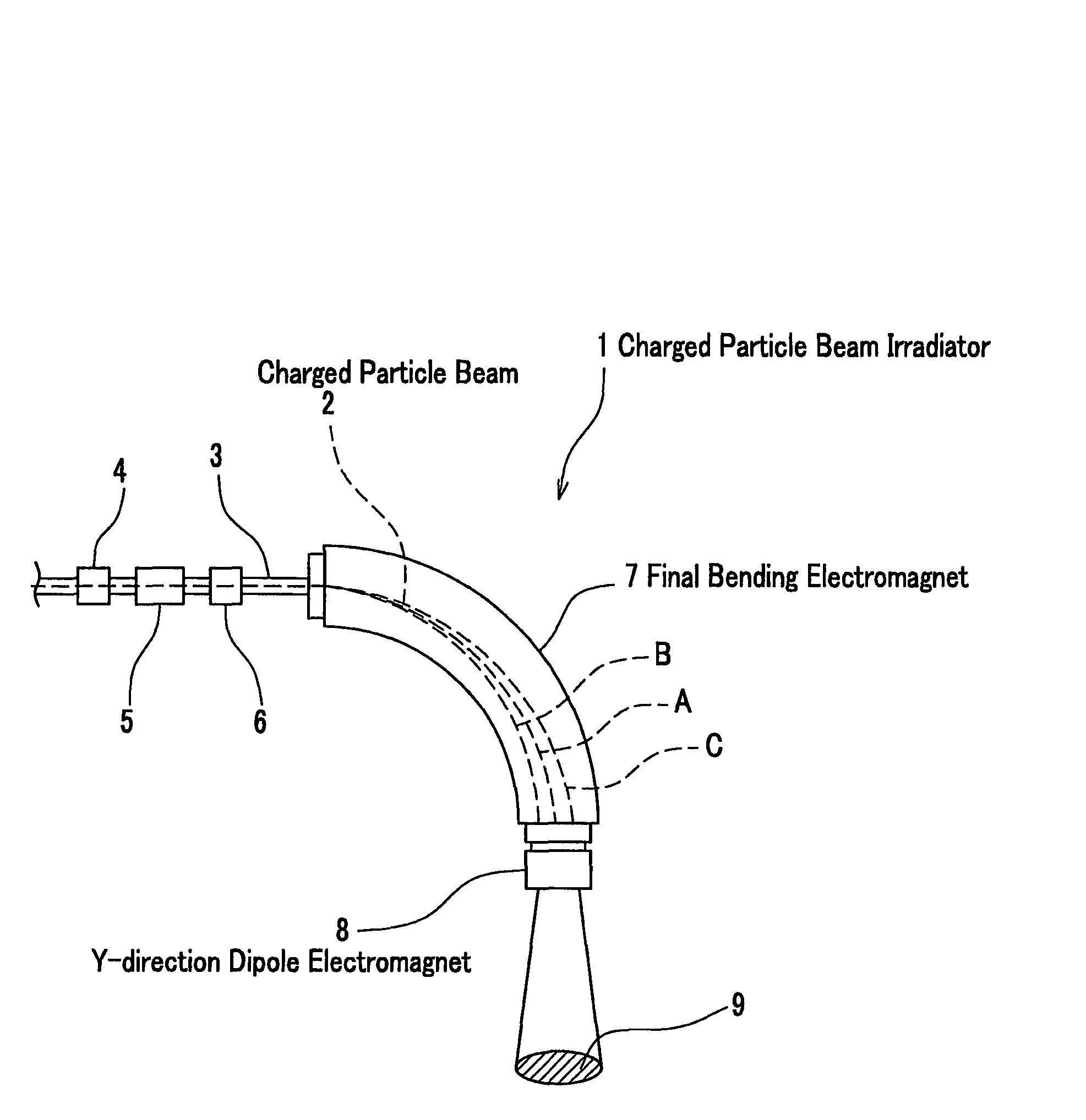
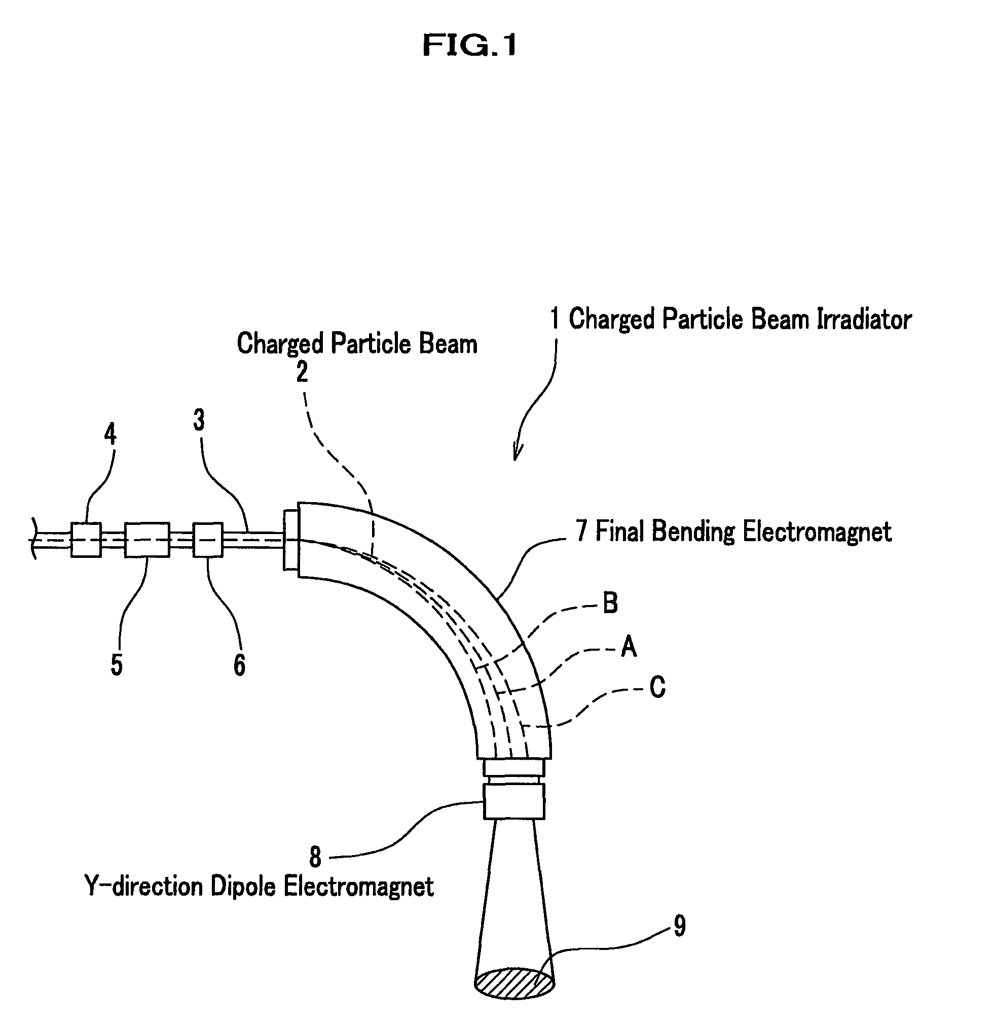
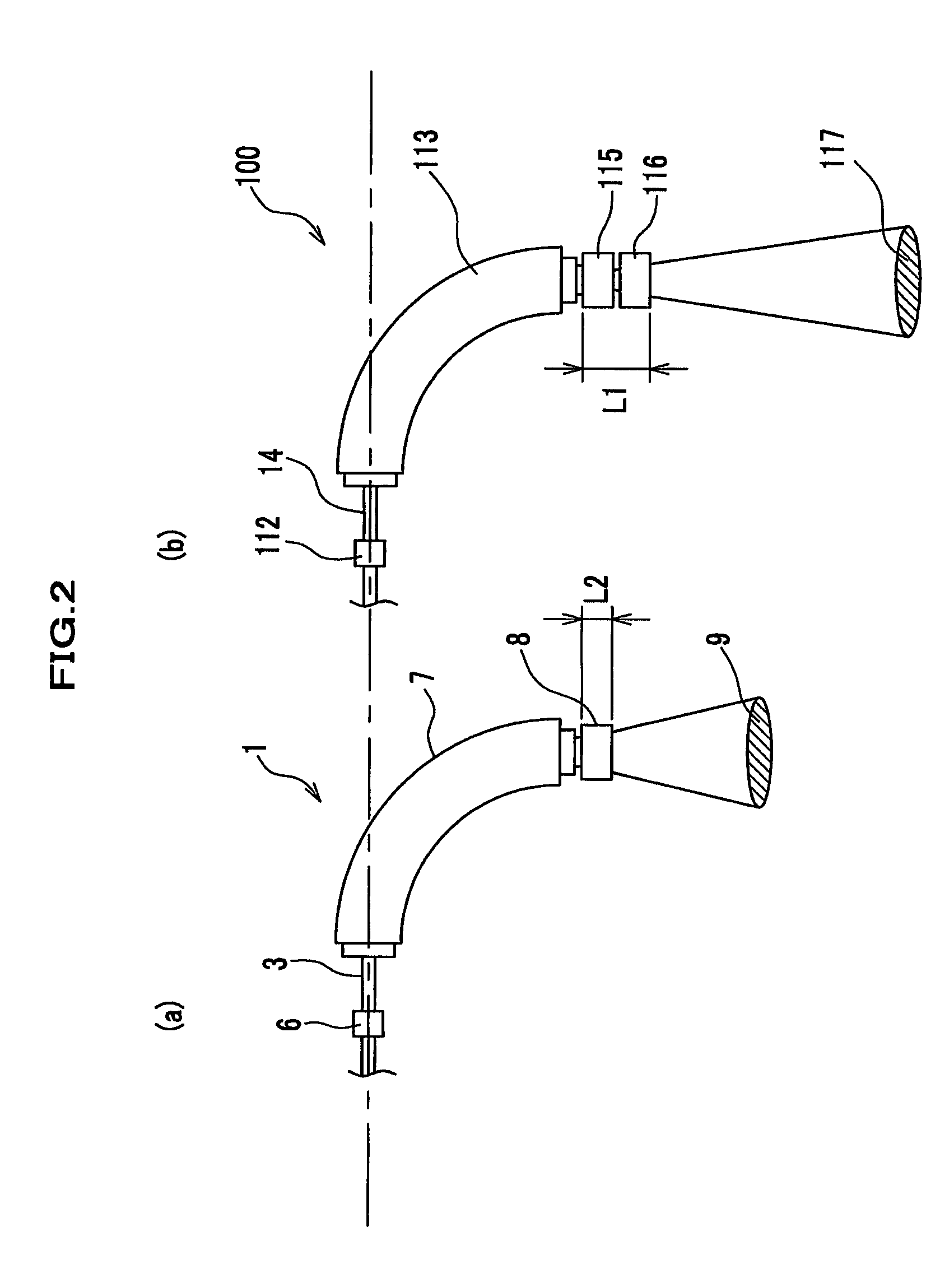
[0023]A description is given, referring to the attached drawings FIG. 1 and FIG. 2, on a charged particle beam irradiator according to the first embodiment of the present invention. FIG. 1 is a drawing illustrating an assembly of an irradiating portion of a charged particle beam irradiator according to the present embodiment. FIG. 2 compares a charged particle beam irradiator according to the present embodiment and a charged particle beam irradiator according to a conventional art, wherein (a) shows the charged particle beam irradiator according to the present embodiment, and (b) shows a charged particle beam irradiator according to the conventional art.

[0024]As illustrated in FIG. 1, in the same way as described in the description of the background art on the charged particle beam irradiator 100, the charged particle beam irradiator 1 includes a beam transfer tube 3 through which a charged particle beam such as a carbon ion beam, etc., travels; quadrupole electromagnets 4, 5, 6 whi...

second embodiment

[0028]Next, FIG. 3 illustrates a second embodiment according to the present invention. FIG. 3 compares a rotary gantry according to the present embodiment and a rotary gantry according to a conventional art.

[0029]As illustrated in FIG. 3, the rotary gantry 50 includes a first bending electromagnet 51; a second bending electromagnet 53 which is connected to the first bending electromagnet 51 through a beam transfer tube 52; quadrupole electromagnets 54, 55, 56 installed along the beam transfer tube 52; a third bending electromagnet (final bending electromagnet, hereinafter) 58 which is connected to the second bending electromagnet 53 through a beam transfer tube 57; quadrupole electromagnets 59, 60, 61 installed along the beam transfer tube 57; and a Y-direction dipole electromagnet 62 which is connected to a downstream side end of the final bending electromagnet 58.

[0030]Meanwhile, as illustrated by virtual lines in FIG. 3, a rotary gantry 200 according to the conventional art inclu...


PUM


Abstract

A charged particle beam 2 which enters a final bending electromagnet 7 after traveling through quadrupole electromagnets 4, 5, 6 travels through the final bending electromagnet 7 in an arc shape path by increasing or decreasing a bending magnetic field generated in the final bending electromagnet 7, with a pre-determined period for example and is scanned in an X-direction. The charged particle beam 2 scanned in the X-direction is scanned in a Y-direction while traveling through a Y-direction Wobbler electromagnet 8. Consequently, the charged particle beam 2 is scanned in the X-direction and the Y-direction, and the target 9 is irradiated with the charged particle beam 2 so that a round field is drawn, for example.

Description

TECHNICAL FIELD[0001]The present invention relates to a charged particle beam irradiator and a rotary gantry, for treating a cancer by irradiating cancer cells of a patient with a charged particle beam, for example.BACKGROUND ART[0002]Conventionally, for treating a cancer by a radiation ray, an X-ray, a gamma ray and an electron beam, etc., have been applied, and in recent years, a charged particle beam irradiator which treats a cancer, etc., using a high energy charged particle beam (such as a carbon ion beam, etc.,) accelerated by an accelerator has been developed (refer to non-patent document 1).[0003]Here, a description is given on a charged particle beam irradiator 100 as described above, referring to FIG. 4 and FIG. 5. As illustrated in FIG. 4, charged particles which are accelerated with high energy while traveling through an accelerator (not illustrated) such as a synchrotron, etc., enter a final bending electromagnet, after traveling through quadrupole electromagnets 110, 1...

Claims


Application Information

Patent Timeline
Patent Type & Authority Patents(United States)
IPC IPC(8): H01J1/50
CPCA61N5/10A61N5/1081H05H7/04G21K5/04A61N2005/1087
Inventor FURUKAWA, TAKUJINODA, KOUJI
Owner NAT INST OF RADIOLOGICAL SCI
Why Eureka
Try Eureka