
Vehicle trajectory visualization system

a vehicle trajectory and visualization system technology, applied in the direction of navigation instruments, distance measurement, instruments, etc., can solve the problems of inability to accurately determine whether the vehicle meets the desired requirements, the vehicle is difficult to ensure the planned path and sequence the waypoints correctly, and it is difficult to evaluate the effectiveness of the desired vehicle travel trajectory

Active Publication Date: 2011-03-22
HONEYWELL INT INC
View PDF13 Cites 13 Cited by
  • Summary
  • Abstract
  • Description
  • Claims
  • Application Information

AI Technical Summary

Problems solved by technology

In the process of watching the planned operations of a vehicle (e.g. unmanned) as it flies, drives, burrows, floats, or maneuvers through a medium, it is difficult to ensure the vehicle remains on the planned path and sequences the waypoints correctly.
Without a visualization system to view the planned versus actual trajectory, waypoints and other information regarding vehicle operations, one cannot accurately determine whether the vehicle meets the desired requirements.
As the vehicle travels out of sight, it becomes more difficult to evaluate the desired vehicle travel trajectory effectiveness (waypoint time of arrival, deviations from plan, etc.).
Vehicle waypoints are difficult for people to visualize, as are vehicle trajectories.

Method used


Image

  • Vehicle trajectory visualization system
  • Vehicle trajectory visualization system
  • Vehicle trajectory visualization system

Examples


Embodiment Construction

[0016]Aspects of the present invention provide systems and methods for displaying real-time vehicle orientation, position, and velocity information, as well as planned waypoint markers and past trajectory information.

[0017]Although the following disclosure will make reference to specific wireless transmission protocols and rates, 3D rendering system details, and database operation information, other comparable data communication methods and systems may be used. Particular configurations and protocols discussed in examples can be varied and are merely cited to illustrate an embodiment of the present invention and are not intended to limit the scope of the invention.

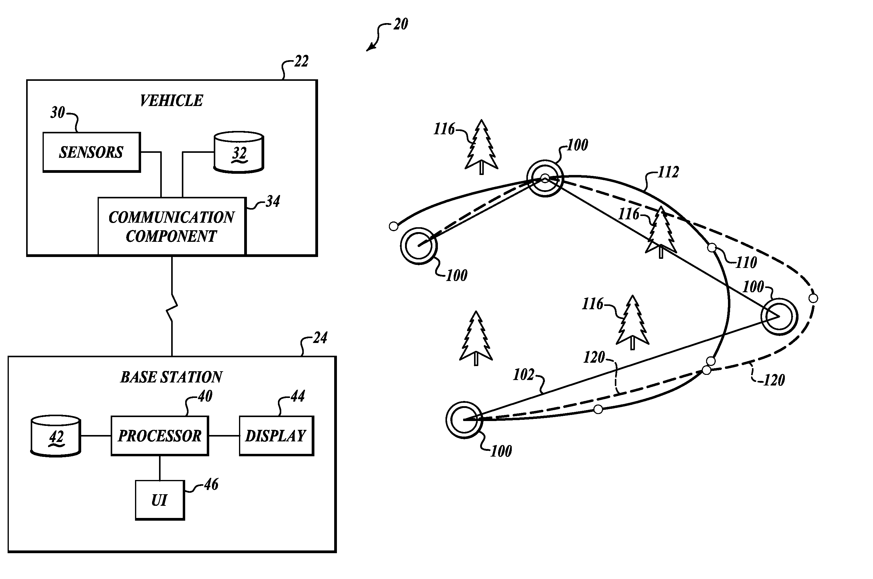
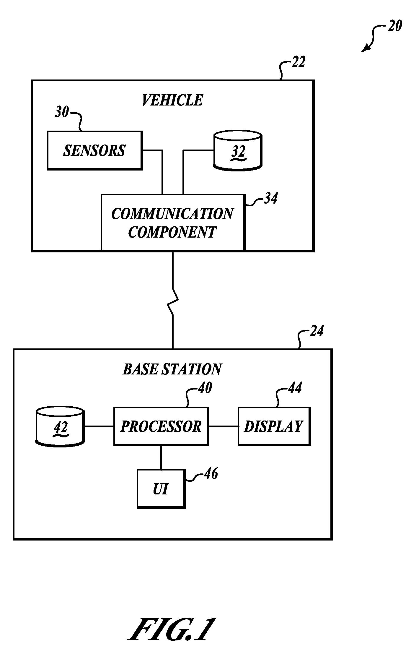
[0018]FIG. 1 shows a vehicle trajectory visualization system 20 that performs real-time monitoring and presentation of a vehicle's trajectory and evaluation of its waypoint sequencing correctness. The system 20 includes a vehicle 22 in signal communication with the base station 24. The vehicle 22 includes sensors 30 and a ...


PUM


Abstract

A vehicle trajectory visualization system capable of displaying real-time (or recorded) vehicle orientation, position, velocity, and waypoint data using a 3D rendering system. The aforementioned data is transmitted from the vehicle to a base station that processes and manipulates the data prior to 3D rendering and insertion into a database. Due to the storing of the vehicle trajectory data, playback of past trajectories is possible, enabling enhanced visual After-Action Review. This system provides instant visual inspection of any virtual or real vehicle's planned trajectory and waypoints versus actual traveled trajectory.

Description

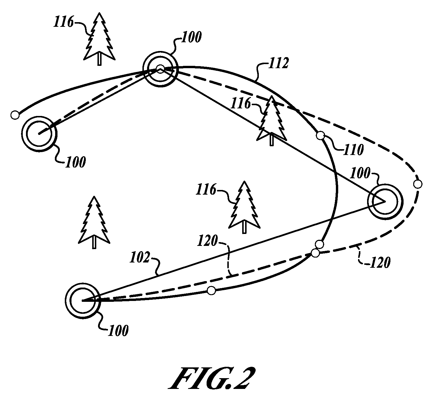
BACKGROUND OF THE INVENTION[0001]In the process of watching the planned operations of a vehicle (e.g. unmanned) as it flies, drives, burrows, floats, or maneuvers through a medium, it is difficult to ensure the vehicle remains on the planned path and sequences the waypoints correctly. Without a visualization system to view the planned versus actual trajectory, waypoints and other information regarding vehicle operations, one cannot accurately determine whether the vehicle meets the desired requirements. As the vehicle travels out of sight, it becomes more difficult to evaluate the desired vehicle travel trajectory effectiveness (waypoint time of arrival, deviations from plan, etc.). Vehicle waypoints are difficult for people to visualize, as are vehicle trajectories.[0002]Therefore, there exists a need for a visualization system that tracks vehicle position, orientation, and velocity, shows planned versus actual trajectory, visualizes waypoints and waypoint sequencing, etc. with rea...

Claims


Application Information

Patent Timeline
Patent Type & Authority Patents(United States)
IPC IPC(8): G05D1/00G01C21/32
CPCG05D1/0044G08G5/0013G08G5/0026
Inventor GOOSSEN, KATHERINELEO, MAURIZIO
Owner HONEYWELL INT INC
Learn More