Feeding apparatus

a technology of feeding apparatus and rubber coating, which is applied in the direction of mechanical control devices, process and machine control, instruments, etc., can solve the problems of more likely to catch the end of the rubber coating steel sheet b>102/b> is more likely to be caught, etc., and achieves the effect of reliably receiving the subsequent sheet pieces and carrying out smoothly

Inactive Publication Date: 2011-03-15
MITSUBISHI HEAVY IND LTD
View PDF8 Cites 0 Cited by
  • Summary
  • Abstract
  • Description
  • Claims
  • Application Information

AI Technical Summary

Benefits of technology

[0014]According to the present invention, when the leading end of the long-formed sheet is in contact with the second feeding section, a relative speed of the second feeding section with respect to a speed of the feeding directional component of the second feeding section included in the delivery speed of the long-formed sheet is made smaller than when the second feeding section is in a resting state. Therefore, the leading end of the long-formed sheet is less likely to be caught by the second feeding section. Specifically, the long-formed sheet is less likely to have accidental delivery such as buckling of the long-formed sheet and snagging of the leading end of the long-formed sheet. As a result, the long-formed sheet can be carried out smoothly.
[0015]According to the present invention, when the leading end of the long-formed sheet is in contact with the second feeding section, the second feeding section slides in a feeding direction with respect to the leading end of the long-formed sheet, thereby the leading end of the long-formed sheet is not caught by the second feeding section. Thus, accidental delivery of the long-formed sheet is less likely to take place.
[0016]According to the present invention, since the second feeding section is not started for operation in a state that sheet pieces are placed on the second feeding section, it is possible to reliably receive subsequent sheet pieces.

Problems solved by technology

In particular, there is a problem that the leading end of the rubber coated steel sheet 102 is made sharper as the cutting angle is made smaller, by which the leading end of the rubber-coated steel sheet 102 is more likely to be caught by the second feeding section.

Method used


Image

  • Feeding apparatus
  • Feeding apparatus
  • Feeding apparatus

Examples


first embodiment

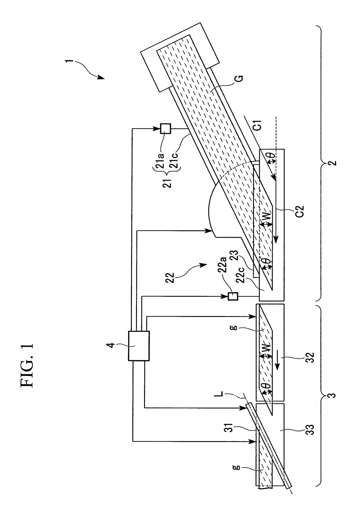
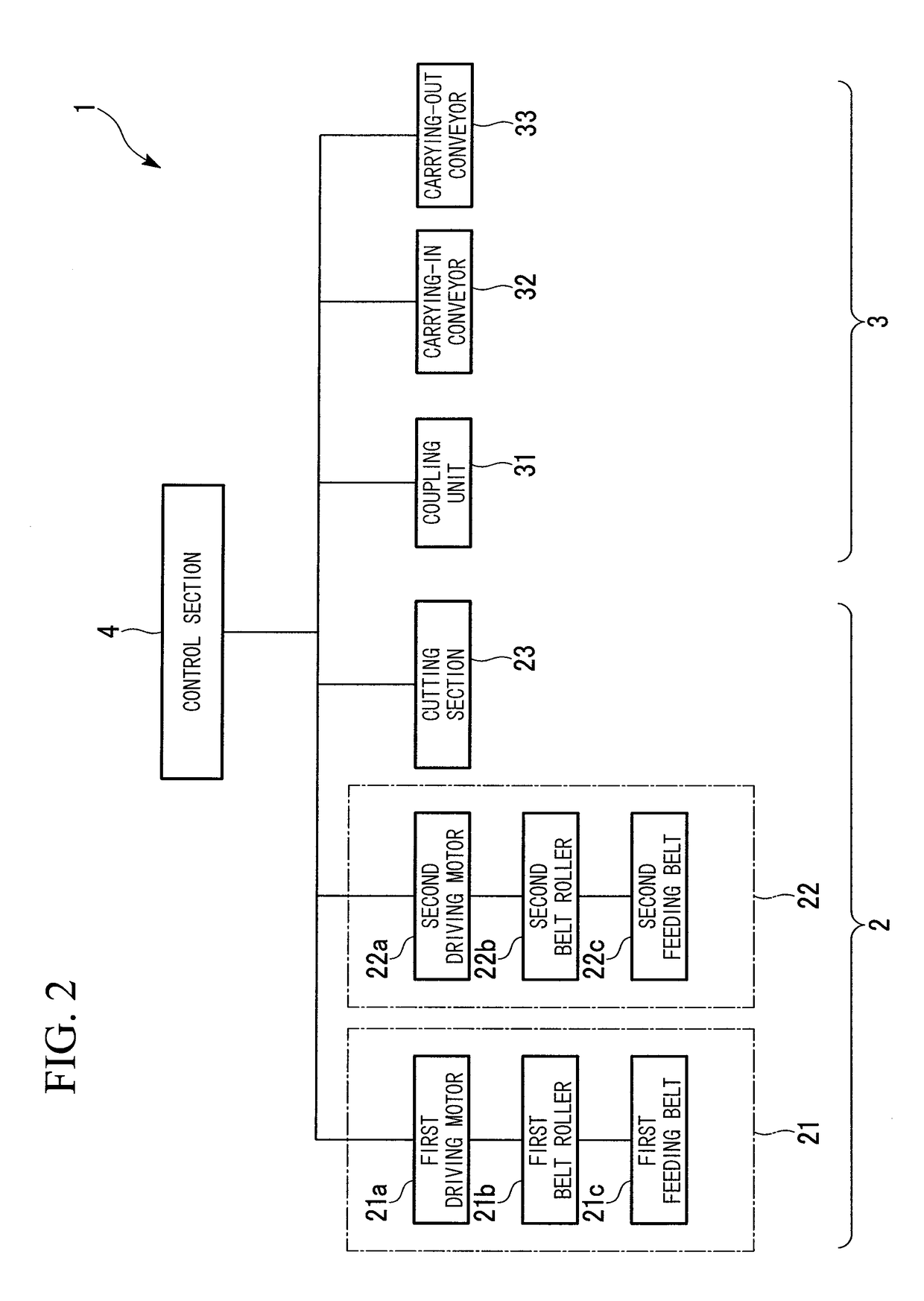
[0022]FIG. 1 is a plan view showing the production facilities 1 of a carcass cord of tires in the first embodiment of the present invention. FIG. 2 is a block diagram of the control the production facilities 1. The production facilities 1 mainly includes a feeding apparatus 2, a coupling apparatus 3, and a control section 4 for controlling them. The production facilities 1 will be briefly described. As shown in FIG. 1, the feeding apparatus 2 cuts a long-formed rubber-coated steel cord (long-formed sheet) G during the feeding process to form cord pieces (sheet pieces) g, thereby carrying out the cord pieces g continuously to the coupling apparatus 3. Then, the coupling apparatus 3 couples the trailing end of a preceding cord piece g with the leading end of a subsequent cord piece g to form a carcass cord.

[0023]As shown in FIG. 1 and FIG. 2, the feeding apparatus 2 is provided with a first feeding section 21, a second feeding section 22 and a cutting section 23.

[0024]The first feedin...

second embodiment

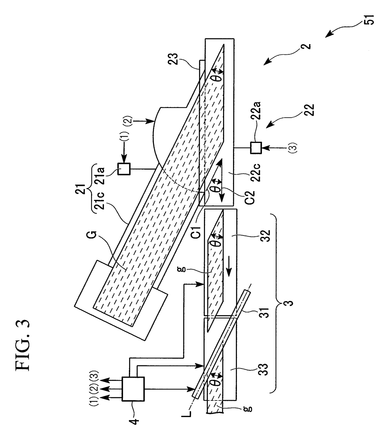
[0048]Subsequently, an explanation will be given for production facilities 51 for a carcass cord of tires in a second embodiment of the present invention. FIG. 3 is a plan view showing the production facilities 51. The same constituents as those described in FIG. 1 and FIG. 2 are given the same symbols or numerals, the explanation of which will be omitted here.

[0049]As shown in FIG. 3, in the production facilities 51, the first feeding section 21 is arranged differently from that arranged in the first embodiment of the production facilities 1. Specifically, the first feeding section 21 is arranged at a position which is in line symmetry with respect to a virtual line orthogonal to the second feeding direction C2 of the second feeding section 22. In other words, an acute angle is made by the first feeding direction C1 of the steel cord G along the feeding route of the first feeding section 21 and the second feeding direction C2 of the cord piece g along the feeding route of the secon...


PUM

PropertyMeasurementUnit
speedaaaaaaaaaa
cutting angleaaaaaaaaaa
angleaaaaaaaaaa

Abstract

The feeding apparatus is provided with a first feeding section for feeding a long-formed sheet in the longitudinal direction of the sheet, a second feeding section for feeding the long-formed sheet delivered from the first feeding section in a direction intersecting obliquely with the feeding direction of the first feeding section and a control section for controlling the first feeding section and the second feeding section so that the second feeding section starts to operate before the leading end of the long-formed sheet delivered from the first feeding section is in contact with the second feeding section.

Description

CROSS-REFERENCE TO RELATED APPLICATIONS[0001]Priority is claimed on Japanese Patent Application No. 2008-88968 filed on Mar. 31, 2008, the content of which is incorporated herein by reference.BACKGROUND OF THE INVENTION[0002]1. Field of the Invention[0003]The present invention relates to a feeding apparatus which is satisfactorily used in the production of rubber-coated steel cords usable as a carcass cord and a breaker cord of tires, for example.[0004]2. Background Art[0005]In facilities for producing a carcass cord and a breaker cord of tires, such a feeding apparatus provided with a first feeding section, a cutting section and a second feeding section is usually driven. The first feeding section feeds a long-formed rubber-coated steel cord in the longitudinal direction. The cutting section cuts the rubber-coated steel cord delivered from the first feeding section at a cutting angle giving a predetermined angle with respect to the longitudinal direction of the rubber-coated steel ...

Claims


Application Information

Patent Timeline
Patent Type & Authority Patents(United States)
IPC IPC(8): B32B41/00
CPCB29D30/46B29D2030/381
Inventor MIYAHARA, HIROSHIAGAWA, JIROTACHIBANA, MAKOTOMIYAMOTO, YOSHINORI
Owner MITSUBISHI HEAVY IND LTD
Why Eureka
Try Eureka