
Fire retardant panel apparatus and method of making and using same

a technology of fire retardant panels and fire retardant sheets, which is applied in fireproofing, lighting and heating apparatus, heating types, etc., can solve the problems of large amounts of standing water trapped in the cavity, the floor panels are heavier, and the plywood panel is rotted,

Active Publication Date: 2011-03-01
MILWAUKEE COMPOSITES INC
View PDF43 Cites 56 Cited by
  • Summary
  • Abstract
  • Description
  • Claims
  • Application Information

AI Technical Summary

Benefits of technology

[0013]Through use of a flame retardant panel, according to the invention, in a mass transit conveyance, such as a rail car or a bus, for example, the underpan and layer of insulation beneath the floor panel, of prior mass transit flooring systems, can be eliminated, while still providing an enhanced flame retardant capability which meets or exceeds applicable government standards. Through use of a flame retardant panel, according to the invention, weight and complexity of a mass transit flooring system are significantly reduced. In addition, a flame retardant panel, according to the invention, provides improved thermal insulation capabilities, and resistance to sound transmission, as compared to prior flame retardant panel constructions. Flame retardant panels, according to the invention, are also inherently more capable of withstanding exposure to water, and provide an improved moisture barrier, as compared to the metal clad plywood floor panels utilized in prior mass transit vehicles.

Problems solved by technology

This construction results in floor panels that are heavier than is desirable.
Also, past experience has shown that, during operation of the mass transit vehicle, the plywood core sometimes is exposed to water, which causes the stainless steel or aluminum sheets to delaminate and the plywood panel to rot.
In some instances, large amounts of standing water would be trapped within the cavity between the underpan and the floor panels.
As noted above, this standing water sometimes damage the floor panels, and could amount to significant dead weight which had to be carried by the mass transit vehicle.

Method used


Image

  • Fire retardant panel apparatus and method of making and using same
  • Fire retardant panel apparatus and method of making and using same
  • Fire retardant panel apparatus and method of making and using same

Examples


Embodiment Construction

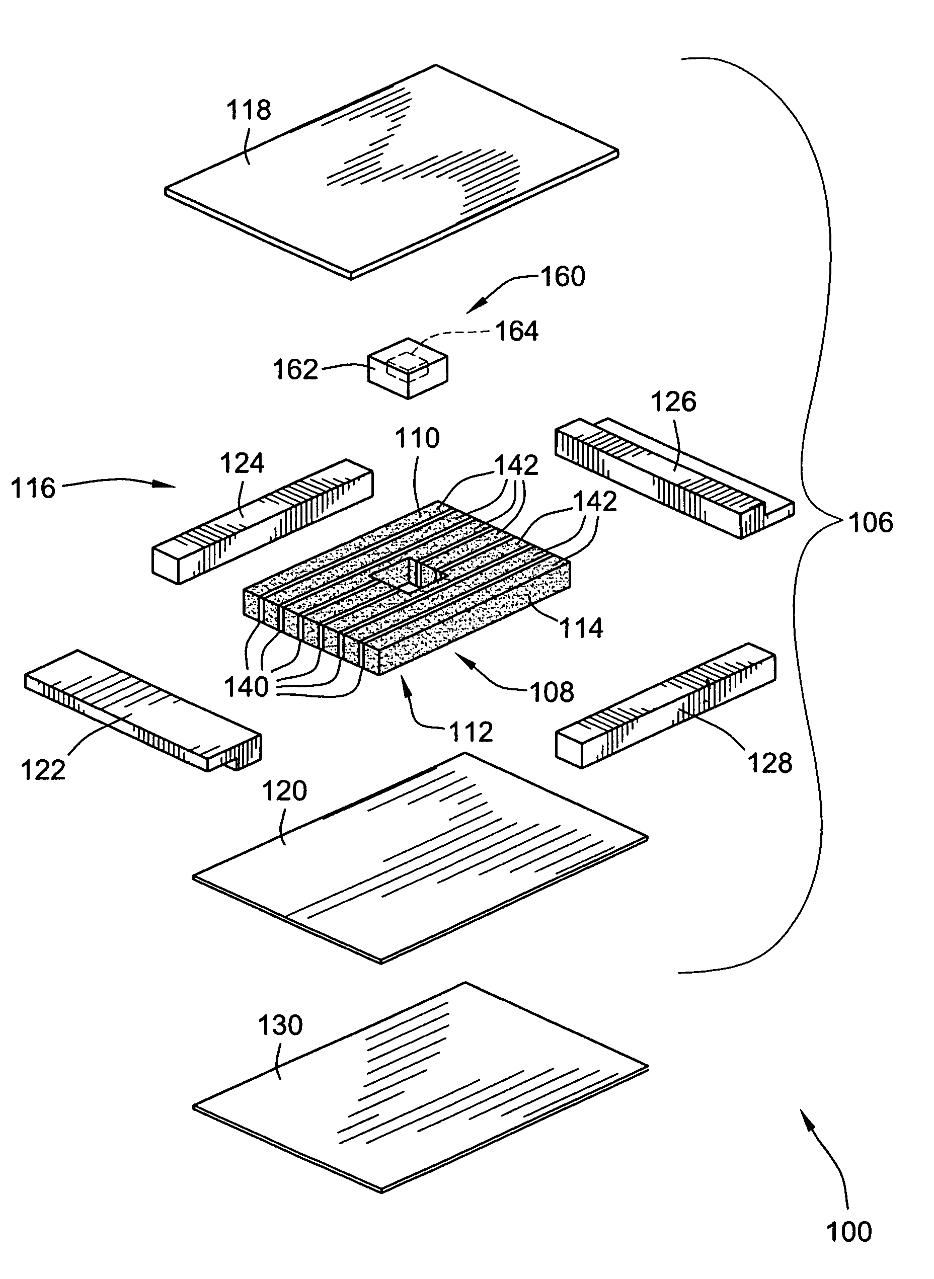
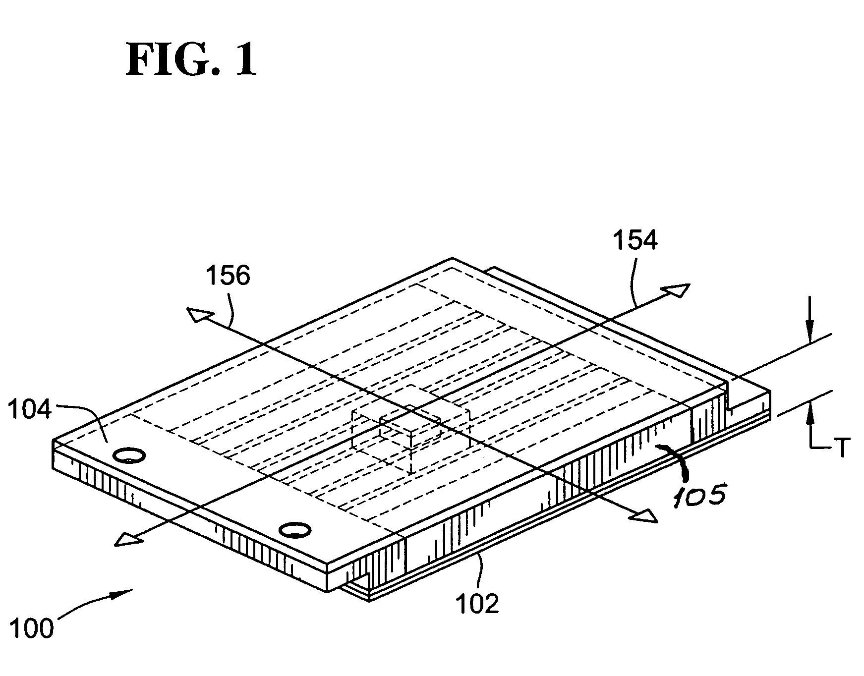
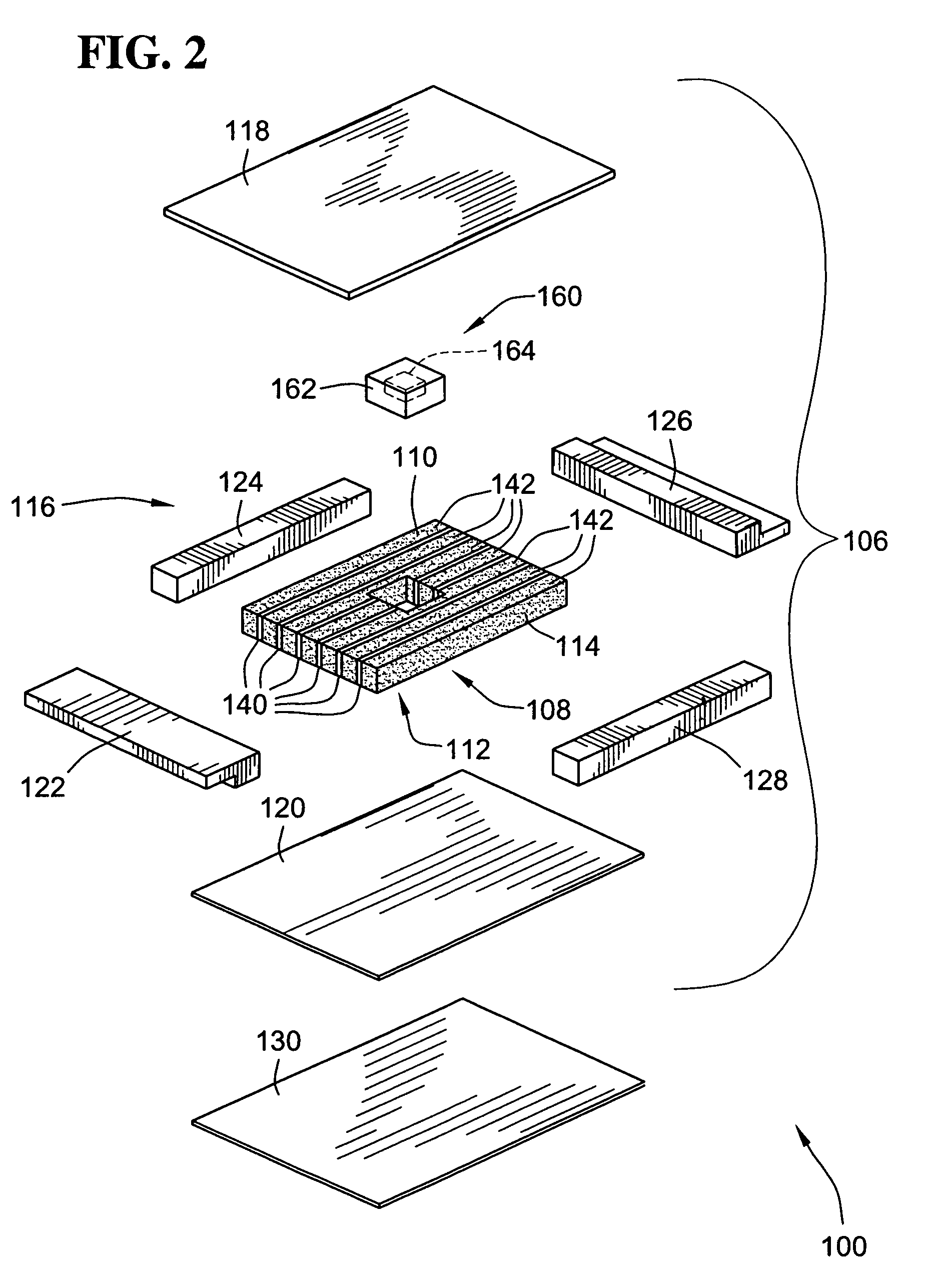
[0047]FIGS. 1 and 2 illustrate a first exemplary embodiment of a flame retardant panel 100, according to the invention, with FIG. 1 showing the flame retardant panel in a completed state, ready for attachment to a support frame, and FIG. 2 illustrating various components of the flame retardant panel 100 in an exploded perspective fashion.

[0048]As shown in FIGS. 1 and 2, the first exemplary embodiment of a flame retardant panel 100, according to the invention, has an exterior face 102 thereof, adapted for attachment to a support frame (not shown), an interior face 104 thereof, adapted for defining a boundary of a compartment and a perimeter 105 thereof extending around the panel 100 between the interior and exterior faces 104, 106 of the panel 100. The flame retardant panel 100 includes a panel structure 106 including a primary core 108 having first and second faces 110, 112 thereof and a periphery 114 thereof. In the first exemplary embodiment of the flame retardant panel, as illust...


PUM

PropertyMeasurementUnit
Volumeaaaaaaaaaa
Volumeaaaaaaaaaa
Volumeaaaaaaaaaa

Abstract

A flame retardant panel apparatus, and method, utilize a flame retardant panel, having an exterior and an interior face thereof, with the panel including a panel structure having a primary core encapsulated within a panel frame of reinforced phenolic material, and a layer of flame retardant material attached to the panel structure and extending outwardly therefrom to at least partially define an exterior face of the flame retardant panel. The flame retardant panel is suitable for use in mass transit conveyances, such as subway cars, high speed cars, rail cars, buses, rapid response vehicles, marine vessels, and elevators.

Description

CROSS-REFERENCE TO RELATED PATENT APPLICATIONS[0001]This patent application claims the benefit of U.S. Provisional Patent Application No. 60 / 703,048, filed Jul. 27, 2005, the disclosure and teachings of which are incorporated herein, by reference, in their entirety.FIELD OF THE INVENTION[0002]This invention relates generally to fire retardant panels, and more particularly to fire retardant panels suitable for use in mass transit conveyances, such as subway cars, high speed cars, rail cars, buses, rapid response vehicles, marine vessels, or elevator cars.BACKGROUND OF THE INVENTION[0003]Public conveyances, such as rail cars, buses, elevators, and the like, are typically subject to government regulations requiring that a passenger compartment of the conveyance be at least partially constructed from fire retardant panels, which provide protection for occupants of the compartment in the event that a fire should occur outside or within the passenger compartment.[0004]For example, in the ...

Claims


Application Information

Patent Timeline
IPC IPC(8): B32B3/02
CPCB60R13/08B61D17/10B66B11/0226E04C2/296E04B1/942Y10T428/239Y10T428/233E04C2/525F24D13/022Y10T29/49002Y02B30/00E04B1/94B32B3/12
Inventor LOCHER, DAVID M.DESING, JAMES E.
Owner MILWAUKEE COMPOSITES INC
Learn More