
Electrode catheter for the electrotherapy of cardiac tissue

a technology of electrotherapy and cardiac tissue, applied in the field of electric catheters, can solve the problems of undesired artifacts, treatment cannot be performed under observation in the course of magnetic resonance tomography, and no longer occurs, and achieve the effect of avoiding tissue injuries

Inactive Publication Date: 2011-03-01
VASCOMED GMBH
View PDF15 Cites 136 Cited by
  • Summary
  • Abstract
  • Description
  • Claims
  • Application Information

AI Technical Summary

Benefits of technology

[0018]An alternative electrode catheter implemented for connection to an implantable defibrillator has at least one defibrillation electrode. Defibrillation electrodes differ from typical stimulation or sensing electrodes, as are connected to a cardiac pacemaker, through their typically significantly larger spatial dimensions, which provide a sufficiently large electrode surface to limit the current density at the typical current strengths required for defibrillation to an amount at which tissue injuries are avoided.

Problems solved by technology

Subsequently, by applying typically high-frequency AC current, which may be output in a targeted way via treatment electrodes, tissue erosion (ablation) may be caused, with the result that stimulus conduction no longer occurs where the cardiac tissue is eroded.
Corresponding catheters and treatments are known in principle and have had the great disadvantage up to this point that the treatment cannot be performed under observation in the course of magnetic resonance tomography, since the electrical lines between the proximal end of the electrode catheter and the electrodes at the distal end of the electrode catheter may heat up significantly as a result of induction currents induced by the magnetic resonance tomography.
In addition, the electrical conductors of the typical electrode catheters result in undesired artifacts in the image recorded using magnetic resonance tomography.
This problem is all the greater since the maximum power consumption of the electrical lines is given when their length is a multiple of half of the wavelength output by the magnetic resonance tomograph, i.e.,
A further difficulty is that the greatest heating occurs precisely in proximity to the distal end of the corresponding electrode catheter in the area between endocardium and myocardium.
Up to this point, these reasons have resulted in electrophysiological examination of the myocardium or electrotherapy of the myocardium in the form of ablation or similar treatments not being able to be performed under observation in magnetic resonance tomographs.
Similar problems also result in connection with stimulation electrode catheters or defibrillation electrode catheters for connection to an implantable cardiac pacemaker, cardioverter, defibrillator, or the like.
Since typical defibrillation and stimulation electrode catheters are not compatible with magnetic resonance, the patients having such implants may not be examined using a magnetic resonance tomograph.

Method used


Image

  • Electrode catheter for the electrotherapy of cardiac tissue
  • Electrode catheter for the electrotherapy of cardiac tissue
  • Electrode catheter for the electrotherapy of cardiac tissue

Examples


Embodiment Construction

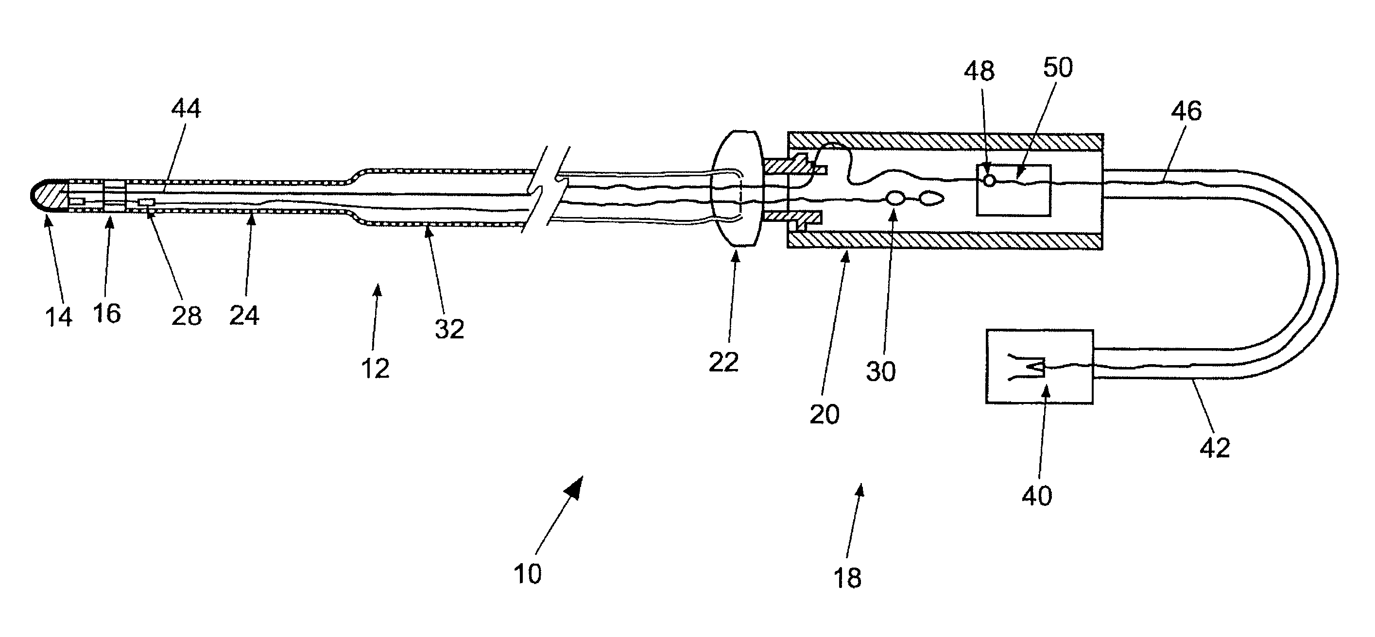
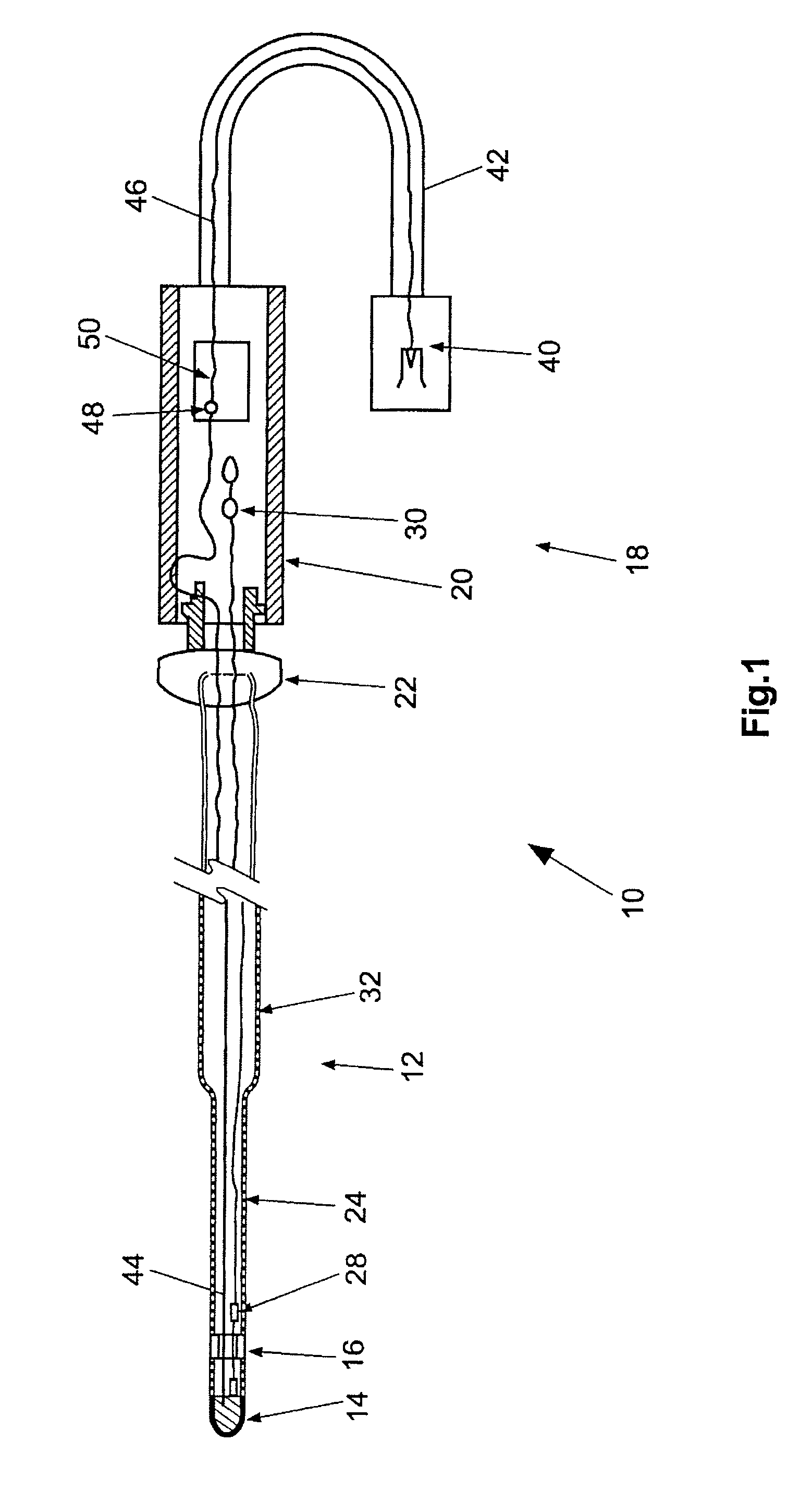
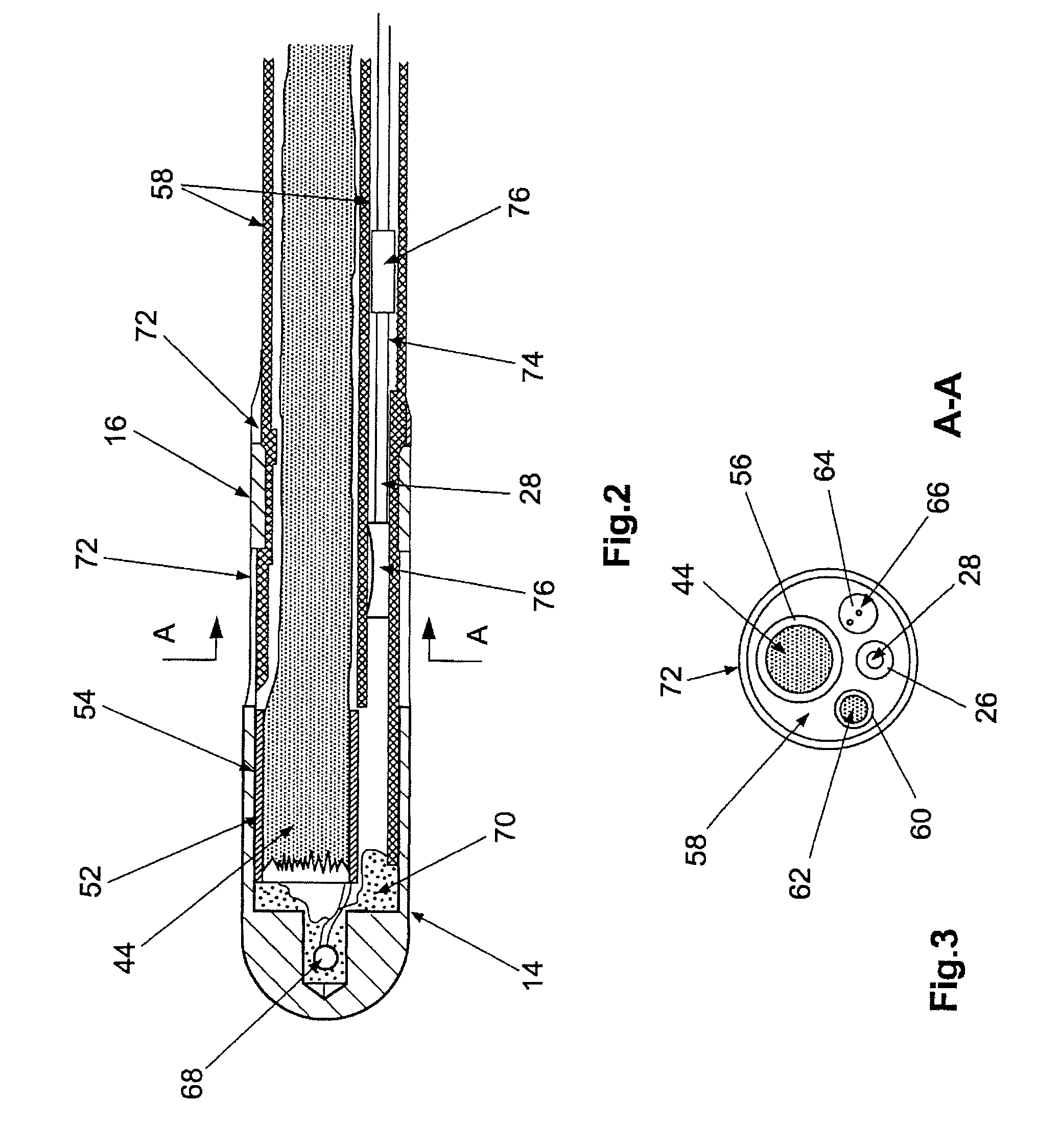
[0046]The ablation catheter 10 illustrated in FIG. 1 has a catheter shaft 12, which is also identified as an electrode catheter 12 in the framework of this description and the claims. The electrode catheter 12 carries two electrodes on its distal end, namely a tip electrode 14 and a ring electrode 16. The tip electrode 14 and the ring electrode 16 are used in the case of tissue erosion (ablation) for delivering high-frequency AC current to surrounding tissue in order to heat the tissue using the AC current enough that it erodes.

[0047]At the proximal end, the electrode catheter 12 is connected to a handle 18, which has a holding part 20 and a displacement part 22. Holding part 20 and displacement part 22 are displaceable in relation to one another in a known way in the longitudinal direction of the holding part 20 in order to cause lateral deflection of a distal end section 24 of the electrode catheter 12. This is performed in a way known in principle with the aid of a control wire 2...


PUM


Abstract

The present invention relates to an electrode catheter for defibrillation, mapping or ablation of cardiac tissue. Said catheter comprises a terminal (40) on the proximal end of the electrode catheter and one or more sensing and / or treatment electrodes (14, 16) that are situated on or in the vicinity of the distal end of the electrode catheter, in addition to at least one electric conductor (44, 62), which is used to electrically connect a respective sensing or treatment electrode to the terminal. The electric conductor (44, 62) is composed of carbon and the electrode catheter is configured to be suitable for us as part of magnetic resonance tomography and for connection to electrophysiotherapy equipment. Said catheter comprises at least one defibrillation electrode, or at least one sensing electrode (14, 16) for the recording and evaluation of cardiac tissue potentials, or at least one treatment electrode (14) for delivering high-frequency currents for ablation purposes.

Description

FIELD OF THE INVENTION[0001]The present invention relates to an electric catheter for the electrotherapy or examination of cardiac tissue, i.e., of myocardium.BACKGROUND OF THE INVENTION[0002]The present invention relates to an electric catheter for the electrotherapy or examination of cardiac tissue, i.e., of myocardium. On its proximal end, the electrode catheter has a terminal, using which the electrode line is connected to an electrical generator, an electrotherapy device, or even to an implant, such as a cardiac pacemaker or defibrillator. The therapy device is preferably a generator for high-frequency current for tissue ablation. On its distal end, the electrode catheter has one or more sensing electrodes or, additionally or alternatively, treatment electrodes.[0003]Electrode catheters of this type are known in particular in the field of electric physiology for detecting and treating stimulus conduction malfunctions in the heart and are also referred to as EP catheters (electr...

Claims


Application Information

Patent Timeline
IPC IPC(8): A61B18/14A61N1/05A61B5/042A61B5/055A61B19/00H01B1/04H01B7/04H01R4/20
CPCA61B18/1492A61N1/056H01B1/04A61B2017/00911A61B2018/00577A61B2019/5236A61N1/0563A61N2001/086A61B2090/374A61N1/086
Inventor HILLER, KARL-HEINZNAHRENDORF, MATTHIASBAUER, WOLFGANG
Owner VASCOMED GMBH
Learn More