Endoscope apparatus
a technology of endoscope and endoscope, which is applied in the field of endoscope devices, can solve the problems that the information of deep tissue near the surface of living body tissue cannot be readily recognized, and achieves the effect of reducing the difficulty of endoscope operation
- Summary
- Abstract
- Description
- Claims
- Application Information
AI Technical Summary
Benefits of technology
Problems solved by technology
Method used
Image
Examples
first embodiment
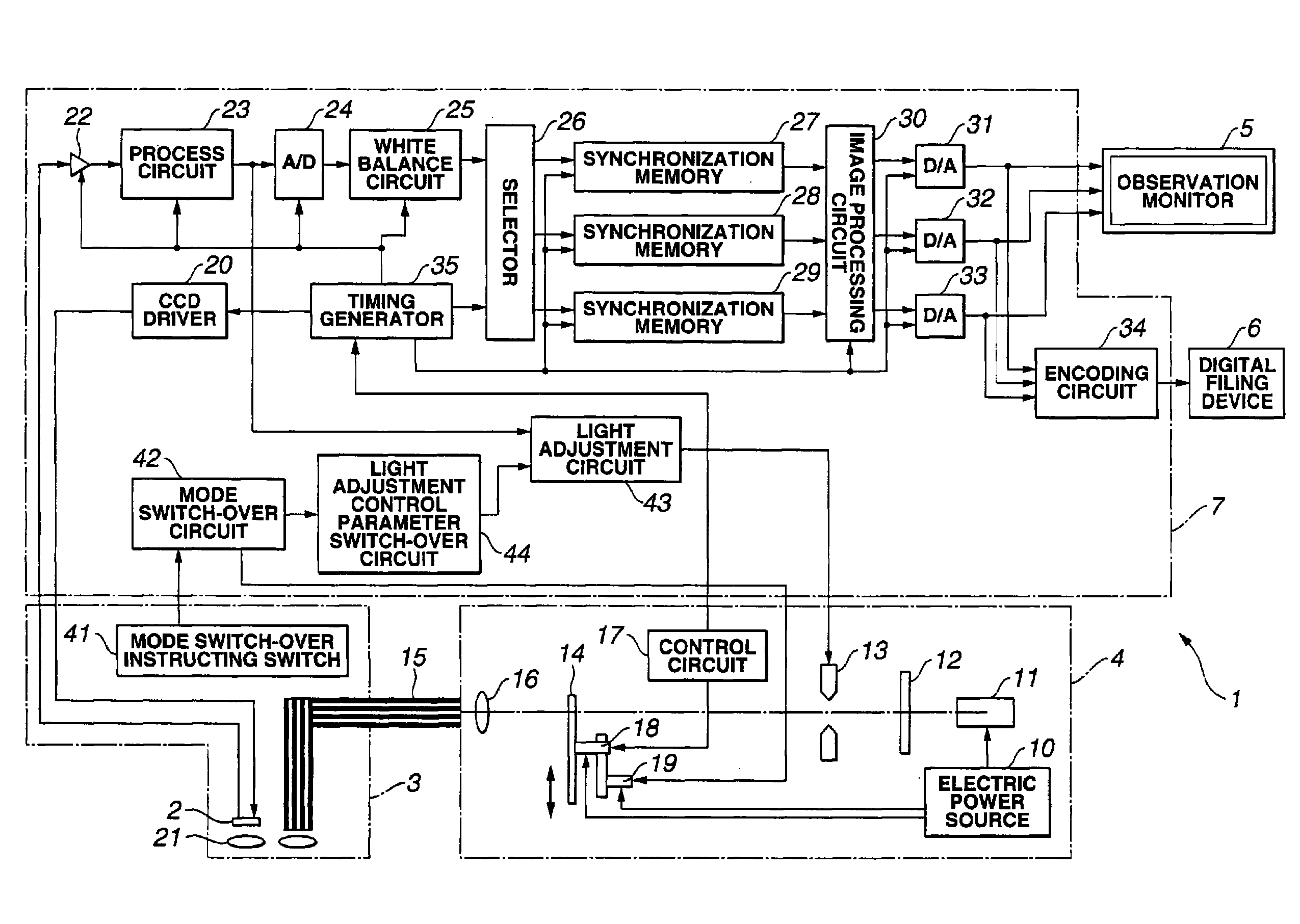
[0115]First, the present invention will be described with reference to FIG. 1 through FIG. 33. Here, FIG. 1 is a configuration diagram illustrating the configuration of an endoscope device, FIG. 2 is a configuration diagram illustrating the configuration of a rotating filter shown in FIG. 1, FIG. 3 is a diagram illustrating the spectral properties of a first filter set of the rotating filter shown in FIG. 2, FIG. 4 is a diagram illustrating the spectral properties of a second filter set of the rotating filter shown in FIG. 2, FIG. 5 is a diagram illustrating the structure of the living body tissue in the layer direction to be observed with the endoscope device shown in FIG. 1, FIG. 6 is a diagram describing the state of the illumination light from the endoscope device shown in FIG. 1 reaching the living body tissue in the layer direction, FIG. 7 is a diagram illustrating each of the band images from frame sequence light transmitted through the first filter set shown in FIG. 3, FIG. ...
second embodiment
[0163]Next, the present invention will be described with reference to FIG. 34 through FIG. 36.
[0164]FIG. 34 is a configuration diagram illustrating the configuration of an endoscope device, FIG. 35 is a configuration diagram illustrating the configuration of the rotating filter shown in FIG. 34, and FIG. 36 is a diagram illustrating the spectral properties of the color chip shown in FIG. 34.
[0165]The second embodiment is almost the same as the first embodiment, so only the differing points will be described, and the same configurations will be denoted with the same reference numerals and description thereof will be omitted.
[0166]As shown in FIG. 34, with the electronic endoscope 3 according to the present embodiment, a color chip 81 is disposed on the front face of the CCD 2, thereby making up a color CCD 2a, configuring an endoscope device 1 of a synchronous system when performing normal observation. Color image signals from the color CCD 2a are converted into color image data at t...
third embodiment
[0171]Next, the present invention will be described with reference to FIG. 37 through FIG. 46.
[0172]FIG. 37 is a configuration diagram illustrating the configuration of an endoscope device, FIG. 38 is a diagram illustrating the band-pass properties of the band restricting filter shown in FIG. 37, FIG. 39 is a diagram illustrating the spectral properties of discrete narrow-band frame sequence light obtained by the band restricting filter shown in FIG. 38, FIG. 40 is a diagram illustrating the band-pass properties of a first modification made on the band restricting filter shown in FIG. 37, FIG. 41 is a diagram illustrating the spectral properties of discrete narrow-band frame sequence light from the band restricting filter shown in FIG. 40, FIG. 42 is a diagram illustrating the band-pass properties of a second modification made on the band restricting filter shown in FIG. 37, FIG. 43 is a diagram illustrating an example of spectral properties of the xenon lamp shown in FIG. 37, FIG. ...
PUM
 Abstract
Description
Claims
Application Information
 - R&D
- Intellectual Property
- Life Sciences
- Materials
- Tech Scout
- Unparalleled Data Quality
- Higher Quality Content
- 60% Fewer Hallucinations
Browse by: Latest US Patents, China's latest patents, Technical Efficacy Thesaurus, Application Domain, Technology Topic, Popular Technical Reports.
© 2025 PatSnap. All rights reserved.Legal|Privacy policy|Modern Slavery Act Transparency Statement|Sitemap|About US| Contact US: help@patsnap.com


