
Starter generator

a technology of starting generator and starting coil, which is applied in the direction of mechanical energy handling, magnetic circuit rotating parts, shape/form/construction, etc., can solve the problems of increasing the temperature inside the cover, affecting the cooling efficiency and possibly exceeding the operating temperature limit of the magnetic sensor. , to achieve the effect of preventing the cooling of the armature coil

Inactive Publication Date: 2011-02-15
KOKUSAN DENKI CO LTD
View PDF12 Cites 18 Cited by
  • Summary
  • Abstract
  • Description
  • Claims
  • Application Information

AI Technical Summary

Benefits of technology

"The present invention provides a starter generator that has a protective cover to waterproof and mechanically protect the rotor and stator while allowing the cooling of the armature coil. The protective cover has a sealed interior with a rotor and stator arranged inside it. The starter generator includes a centrifugal fan to cool the air inside the rotor yoke. The invention also includes a stator bracket that is connected to the engine in a liquid-tight manner. The stator bracket has a base plate and inner and outer peripheral walls to guide air flow. The protective cover has protrusions or heat radiation fins to increase cooling efficiency. Overall, the invention improves the cooling and protection of the starter generator while still allowing it to perform its cooling duties."

Problems solved by technology

However, since it is necessary for the starter generator to generate high torque as a motor at the start of the engine and generate a high output as a generator after the starting operation of the engine is completed, a large amount of heat is kept generating from an armature coil, which causes a rise in temperature of the armature coil.
Therefore, when the starter generator is covered with the protecting cover in liquid-tight manner, the temperature inside of the cover increases largely and possibly exceeds an operating temperature limit of the magnetic sensor.
However, in case of using a starter generator in which a stator is arranged inside of a rotor, the cooling of the armature coil cannot be performed efficiently even if a cooling passage is formed inside of a side wall portion of a protecting cover, as disclosed in USSN2002 / 117,935, since an outer surface of an armature core cannot be contacted with the side wall of the protecting cover.

Method used


Image

  • Starter generator
  • Starter generator
  • Starter generator

Examples


Embodiment Construction

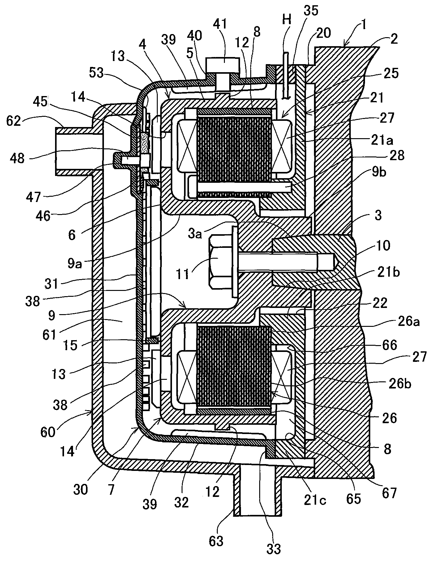
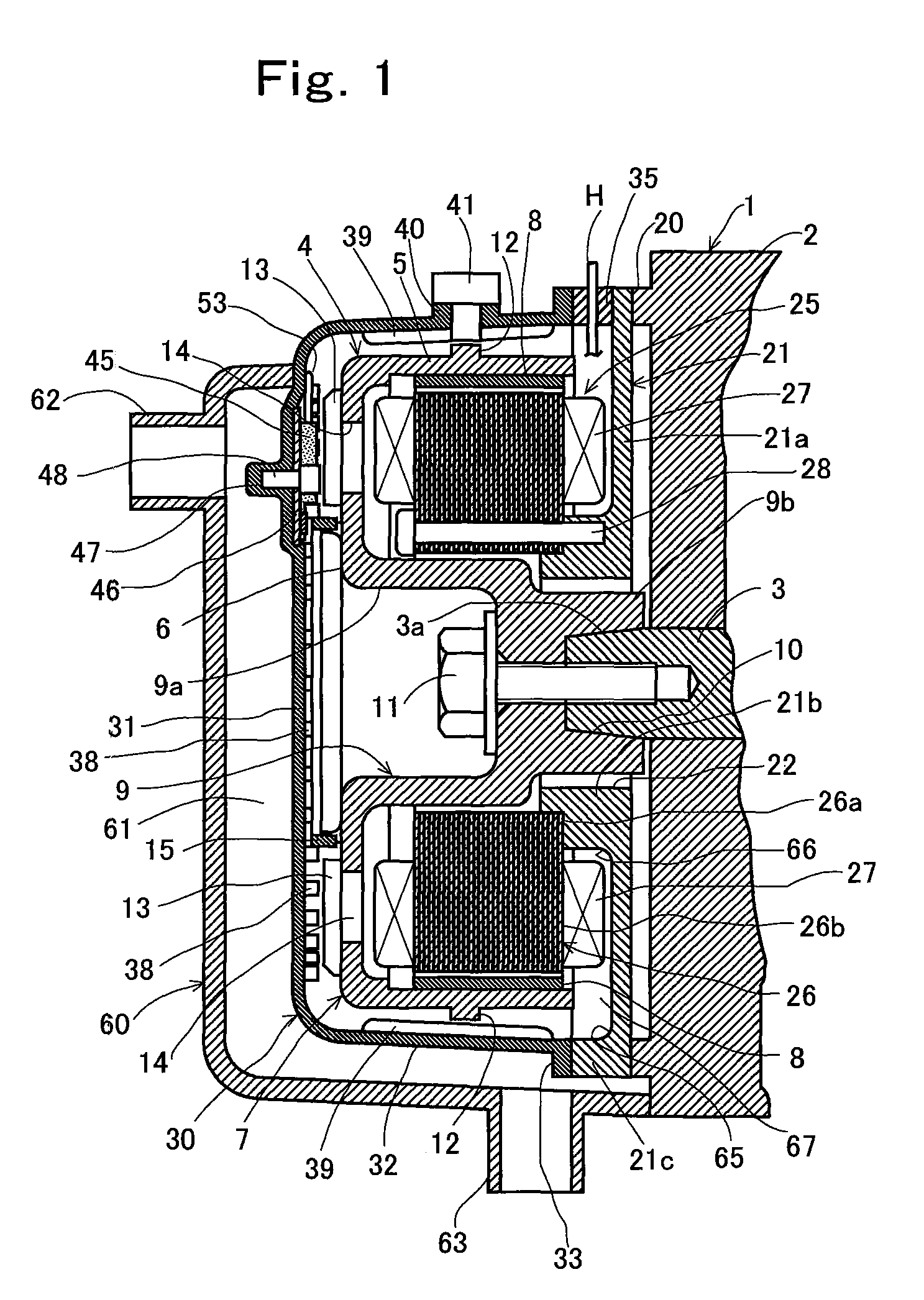
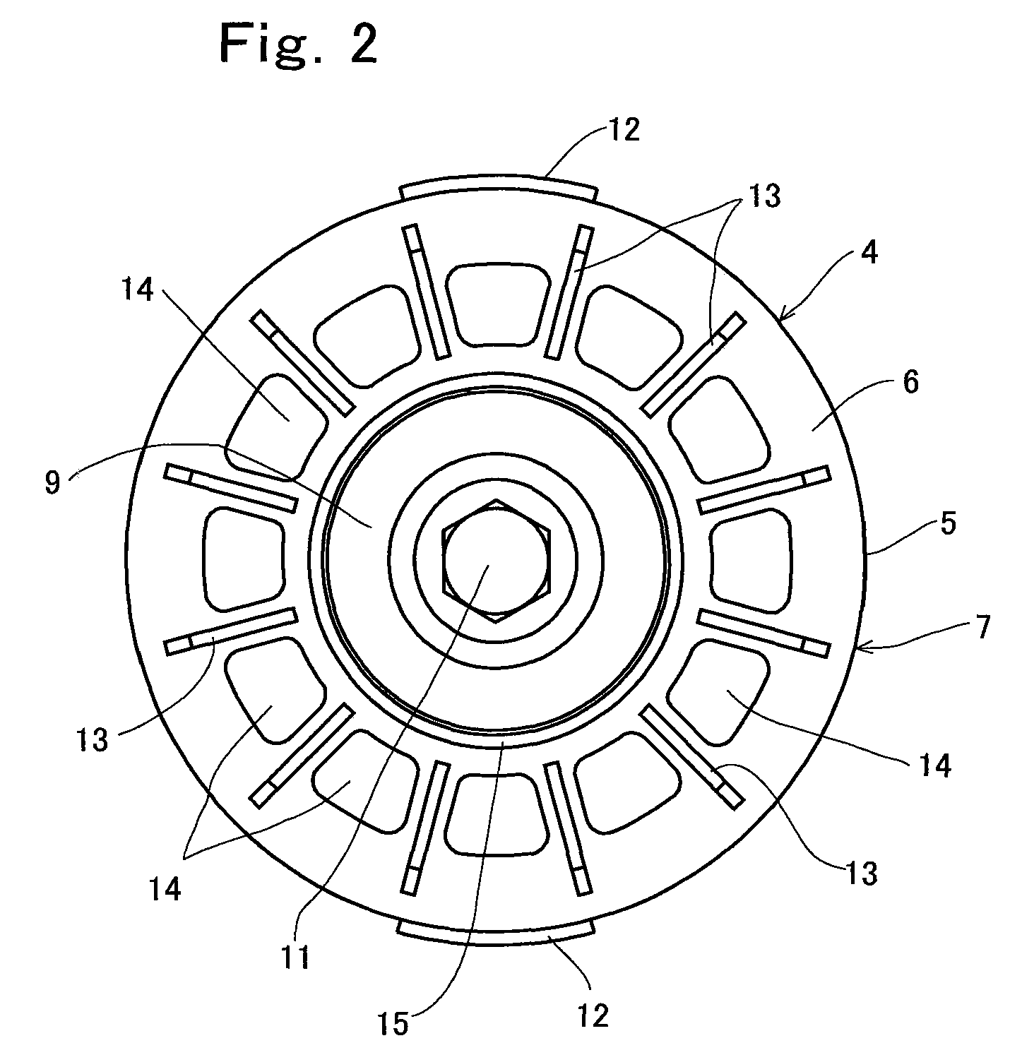
[0035]Now, preferred embodiments of the present invention will be described in detail with reference to the drawings. FIGS. 1 to 6 show a first embodiment of the present invention applied to a starter generator according to the present invention. In FIG. 1, a reference numeral 1 denotes an engine, 2 denotes a crank case of the engine, 3 denotes a crankshaft which is rotatably supported by the crank case. On the crankshaft 3, a rotor 4 is attached. The shown rotor 4 comprises a cup-shaped rotor yoke 7 integrally-having a peripheral wall portion 5 and a bottom wall portion 6 which closes one axial end of the peripheral wall portion 5, and a plurality of arc-shaped permanent magnets 8 which are arranged on an inner periphery of the peripheral wall portion 5 of the rotor yoke 7 at equal angular intervals and are bonded to the peripheral wall portion.

[0036]In the center of the bottom wall portion 6 of the rotor yoke, it is integrally provided a boss 9 consisting of a large-diameter cylin...


PUM


Abstract

A starter generator which includes a rotor having a cuplike-shaped rotor yoke and magnets attached to an inner periphery of the rotor yoke, a stator mounted on a stator bracket and a protecting cover covering said rotor and stator, in which a hermetically sealed casing is constituted by said protecting cover and stator bracket, wherein a plurality of fans are provided on an outer surface of a bottom wall portion of said rotor yoke, a plurality of vent holes are provided through said bottom wall portion, said plurality of fans constitute a centrifugal fan which draws out air inside the rotor yoke through said vent holes and sends the air to an outer periphery of the rotor yoke, and a guide surface which guides the air sent to the outer periphery of the rotor yoke to a space inside the rotor yoke is provided on the stator bracket.

Description

TECHNICAL FIELD OF THE INVENTION[0001]The present invention relates to a starter generator which operates as a starter motor at start of the engine and operates as a magneto generator after the start of the engine.PRIOR ART OF THE INVENTION[0002]It is proposed that a starter generator is mounted on a vehicle driven by an engine. The starter generator is a rotating electric machine which combines a starter motor which drives a crankshaft of the engine at start of the engine with a generator which provides electric power to various electric loads after the starting operation is completed.[0003]As disclosed in U.S. Pat. No. 6,392,311, the starter generator comprises: a rotor which includes a field system consisting of permanent magnets and is mounted on a crankshaft of the engine; a stator having a multi-phase armature coil; a magnetic sensor which outputs signals including rotational angle position information of the rotor; and a drive control system which flow a drive current to the ...

Claims


Application Information

Patent Timeline
Patent Type & Authority Patents(United States)
IPC IPC(8): H02K9/06
CPCH02K5/18H02K5/20H02K7/1815H02K7/006H02K29/08H02K9/12H02K9/19H02K5/203H02K5/207
Inventor TAKAHASHI, MASAKATSUKISHIBATA, KAZUYOSHI
Owner KOKUSAN DENKI CO LTD
Learn More