
GNSS control system and method

a control system and control method technology, applied in the field of gnss applications, can solve the problems of reducing crop yield, under- and over-coverage respectively, and systems involving powerful computers and complex flight and steering controls

Active Publication Date: 2011-02-08
AGJUNCTION
View PDF372 Cites 44 Cited by
  • Summary
  • Abstract
  • Description
  • Claims
  • Application Information

AI Technical Summary

Benefits of technology

The present invention provides a GNSS system and method for guiding and controlling equipment, such as agricultural equipment. The control is based on GNSS positional data, and various types of DGPS controls can be used, including WAAS and other suitable error-correction functionalities. The configuration can be simple with a single DGPS antenna or multiple antennas for additional information corresponding to machine orientation. The technical effect of this invention is to improve the efficiency and accuracy of equipment guiding and control in agricultural applications.

Problems solved by technology

Such sophisticated autopilot and automatic steering systems tend to involve powerful computers and complex flight and steering controls integrated with manual controls.
Gaps and overlaps can occur when operators deviate from the ideal guide paths, resulting in under-coverage and over-coverage respectively.
Such gaps and overlaps are detrimental to agricultural operations and can reduce crop yields.
For example, gaps in coverage reduce the effective areas of fields being cultivated and treated.
Overall crop production may suffer as a result.
Overlaps in coverage tend to be inefficient and wasteful of materials, such as fuel, fertilizer, pesticides, herbicides, seed, etc.
Another potential problem with overlapping coverage relates to the potentially crop-damaging effects of double applications of certain agricultural chemicals.
However, foam marking systems consume foam-making materials and provide only temporary foam marks.
Implements such as spray booms with effective widths of more than 50 feet are in common use, thus increasing the difficulties associated with visually aligning distant, elevated boom ends with foam lines on the ground.
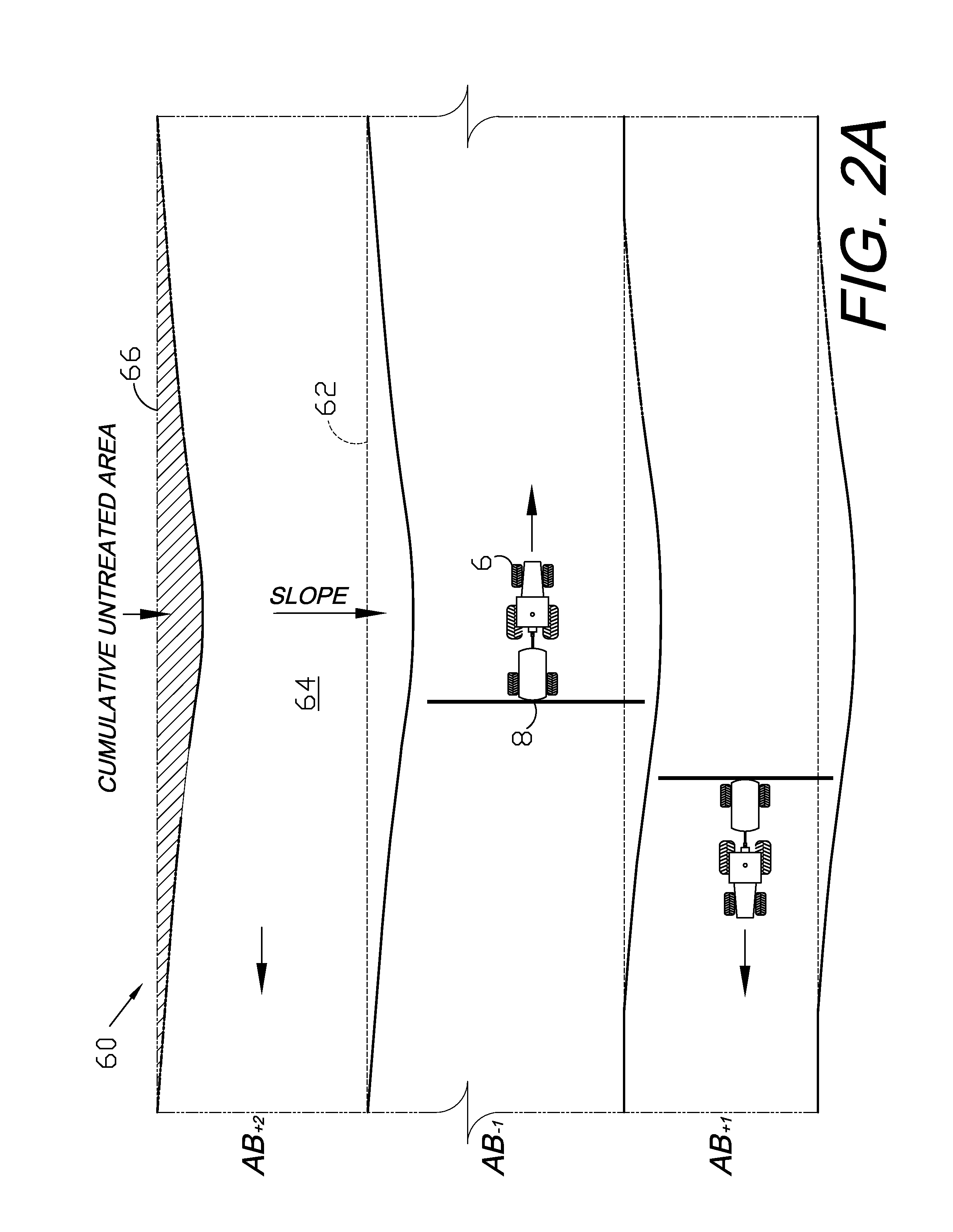
A disadvantage with some of the previous GNSS guidance techniques relates to cumulative error propagation, which can result from machine or operator bias towards one side or the other of the vehicle path, or sloping terrain, which can reduce the effective width (as determined in a horizontal plane) of the implement.
Significant cumulative guidance errors in the form of overlaps and skips can result from such biases being repeated over an entire field.
Another disadvantage with some of the prior art guidance systems relates to their relatively heavy computer processing overhead demands.
Multi-tasking guidance and other automated features, such as steering, tended to require relatively powerful on-board computers programmed with sophisticated software and equipped with large capacity memory devices, all of which tended to increase costs and complexity.

Method used


Image

  • GNSS control system and method
  • GNSS control system and method
  • GNSS control system and method

Examples


Embodiment Construction

I. Introduction and Environment

As required, detailed embodiments of the present invention are disclosed herein; however, it is to be understood that the disclosed embodiments are merely exemplary of the invention, which may be embodied in various forms. Therefore, specific structural and functional details disclosed herein are not to be interpreted as limiting, but merely as a basis for the claims and as a representative basis for teaching one skilled in the art to variously employ the present invention in virtually any appropriately detailed structure.

Certain terminology will be used in the following description for convenience in reference only and will not be limiting. For example, up, down, front, back, right and left refer to the invention as oriented in the view being referred to. The words “inwardly” and “outwardly” refer to directions toward and away from, respectively, the geometric center of the embodiment being described and designated parts thereof. Said terminology will...


PUM


Abstract

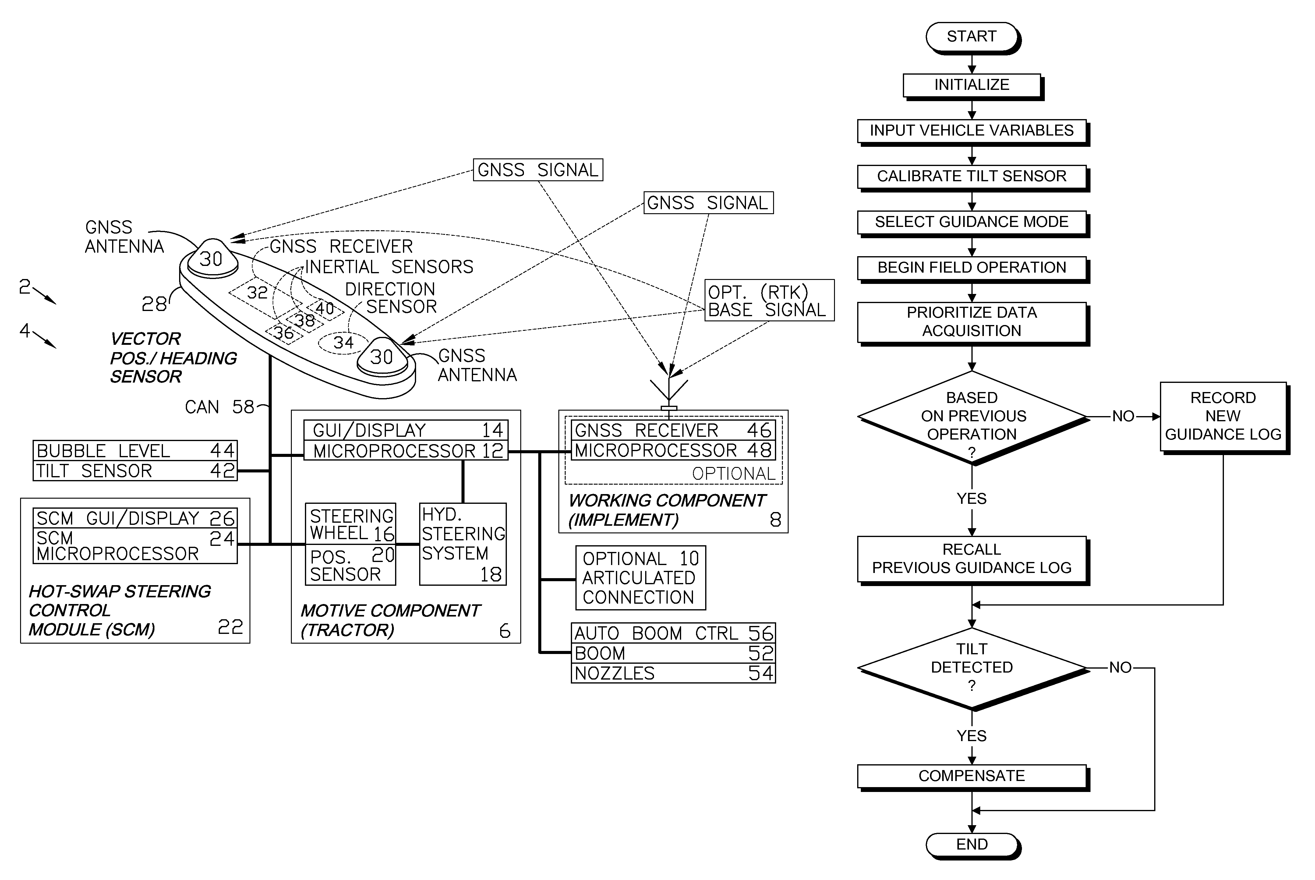
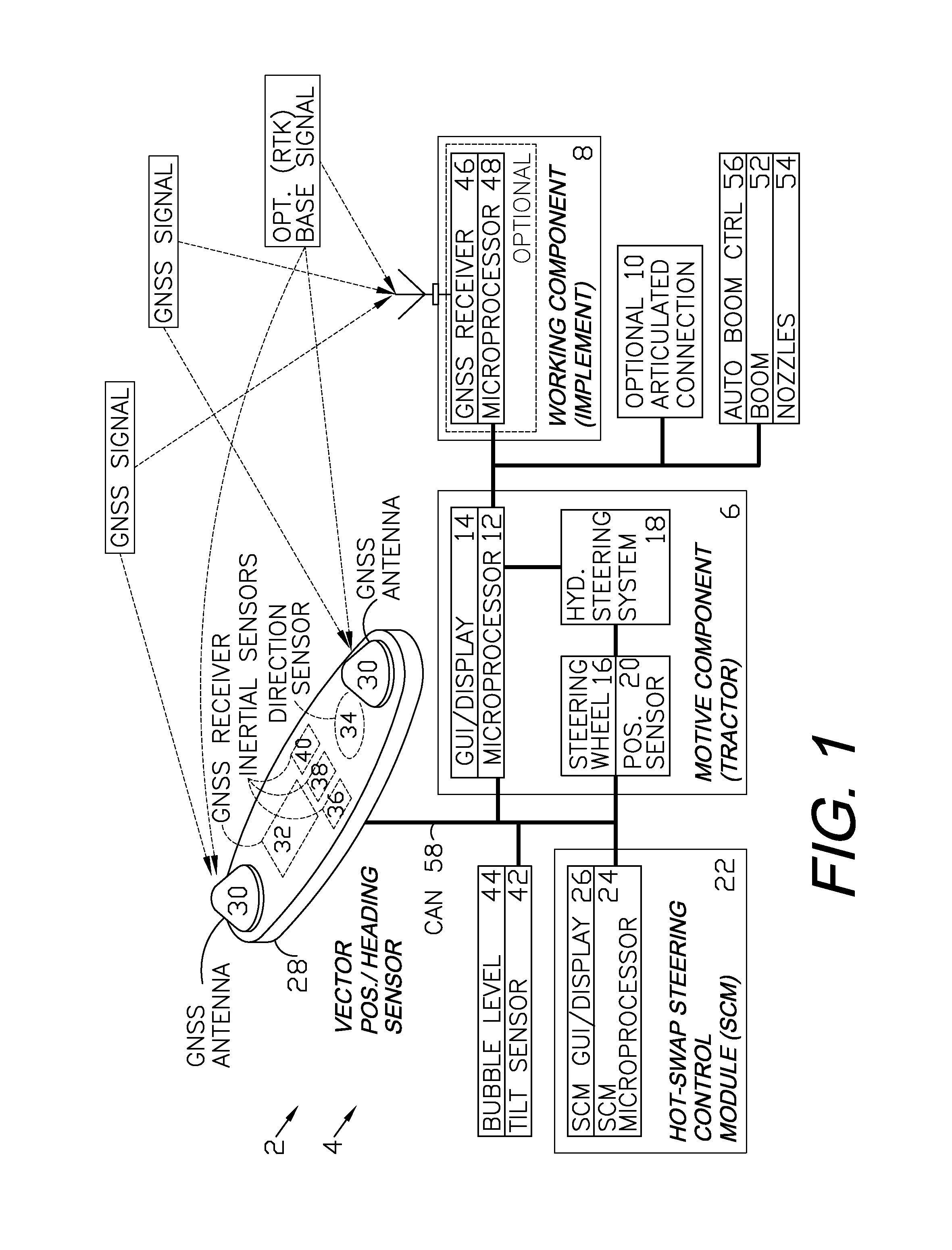
A GNSS control system and method are provided for guiding, navigating and controlling a motive component, such as a tractor, and a working component, such as an implement. A vector position / heading sensor is mounted on the motive component and includes multiple antennas connected to a GNSS receiver. The sensor also includes inertial sensors and a direction sensor, which are connected to a microprocessor of a steering control module (SCM). The SCM can be hot swapped among different vehicles and can interface with their respective original, onboard control systems. The implement can be provided with an optional GNSS antenna, receiver or both, and can be guided independently of the motive component. The SCM can be preprogrammed to guide the vehicle over a field in operating modes including straight line, contour, concentric circle and point+direction. A spray boom with multiple nozzles can be installed on the implement and the nozzles can be independently activated based upon a location of the implement as determined from a log of GNSS data.

Description

BACKGROUND OF THE INVENTION1. Field of the InventionThe present invention relates generally to GNSS applications, including vehicle guidance and navigation.2. Description of the Related ArtThe use of a Global Navigation Satellite System (GNSS) for guidance, navigation and machine control has significantly advanced these fields and enabled a number of applications, including many in agriculture, transportation and other industries. GNSS systems include the Global Positioning System (GPS) and other satellite-based systems. Various GNSS receivers are available for aviation, marine and terrestrial vehicles. The GNSS information provided by such receivers can be processed and used for navigation. In more sophisticated systems, vehicle guidance can be automatically controlled using such information. For example, a predetermined travel or flight path can be programmed into an on-board computer. The vehicle guidance system can automatically maintain appropriate course parameters, such as co...

Claims


Application Information

Patent Timeline
Patent Type & Authority Patents(United States)
IPC IPC(8): G06F7/70G06F7/76G06G7/00G01S19/48
CPCG01C21/005
Inventor MCCLURE, JOHN A.HEINIGER, RICHARD W.FUNK, KENT D.TIMM, JOHN T. E.WONG, RICHARD B.COLLINS, DENNIS M.
Owner AGJUNCTION
Learn More