
Turbofan engine assembly and method of assembling same

a technology of turbine engines and parts, applied in the direction of machines/engines, marine propulsion, vessel construction, etc., can solve the problems of increasing the overall stage count, increasing the overall weight, increasing the design complexity, and/or the manufacturing cost of such an engin

Inactive Publication Date: 2011-02-08
GENERAL ELECTRIC CO
View PDF15 Cites 126 Cited by
  • Summary
  • Abstract
  • Description
  • Claims
  • Application Information

AI Technical Summary

Benefits of technology

This design achieves maximum engine efficiency by optimizing rotational speeds and reducing weight and manufacturing costs through the use of gearboxes, while maintaining assembly simplicity and providing acoustic benefits.

Problems solved by technology

However, while the use of a counter-rotating low-pressure turbine increases the overall engine efficiency, the counter-rotating low-pressure turbine also increases the overall stage count, thus increasing the overall weight, design complexity, and / or manufacturing costs of such an engine are increased.

Method used


Image

  • Turbofan engine assembly and method of assembling same
  • Turbofan engine assembly and method of assembling same
  • Turbofan engine assembly and method of assembling same

Examples


Embodiment Construction

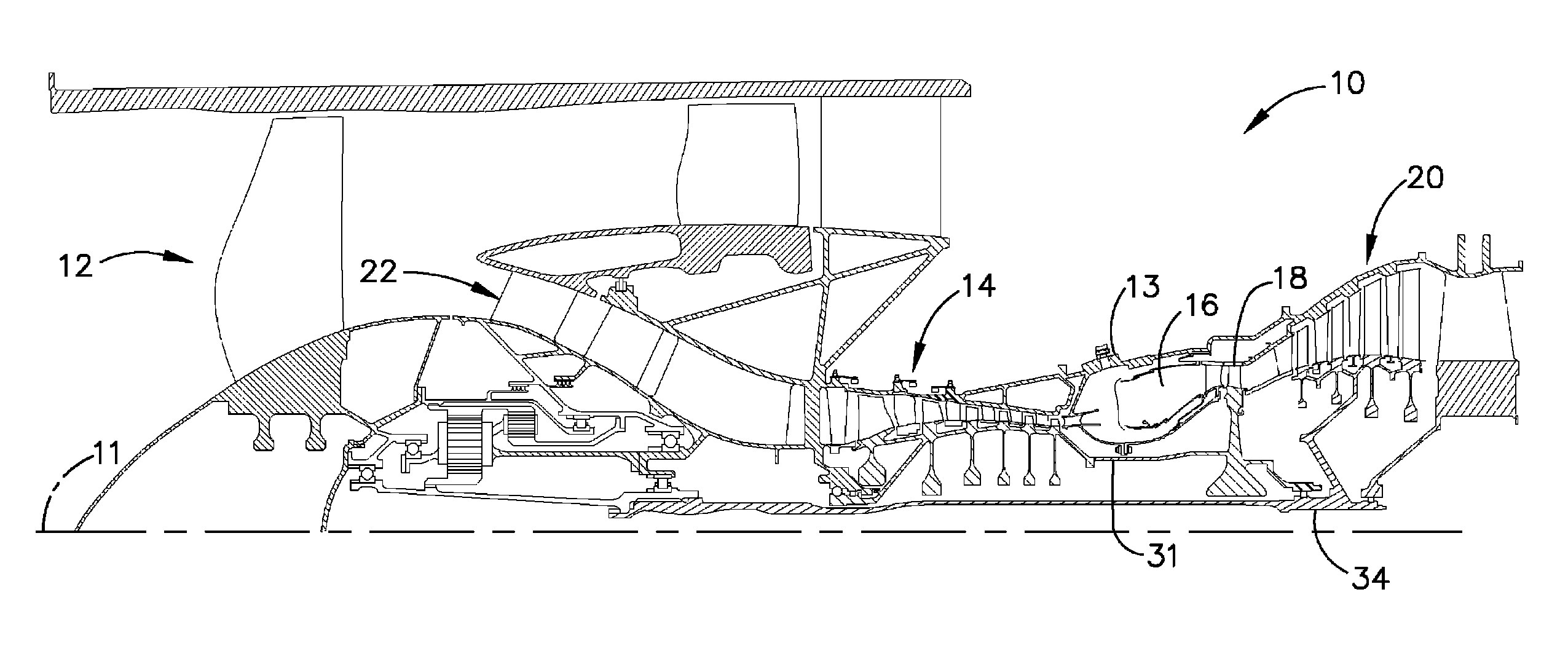
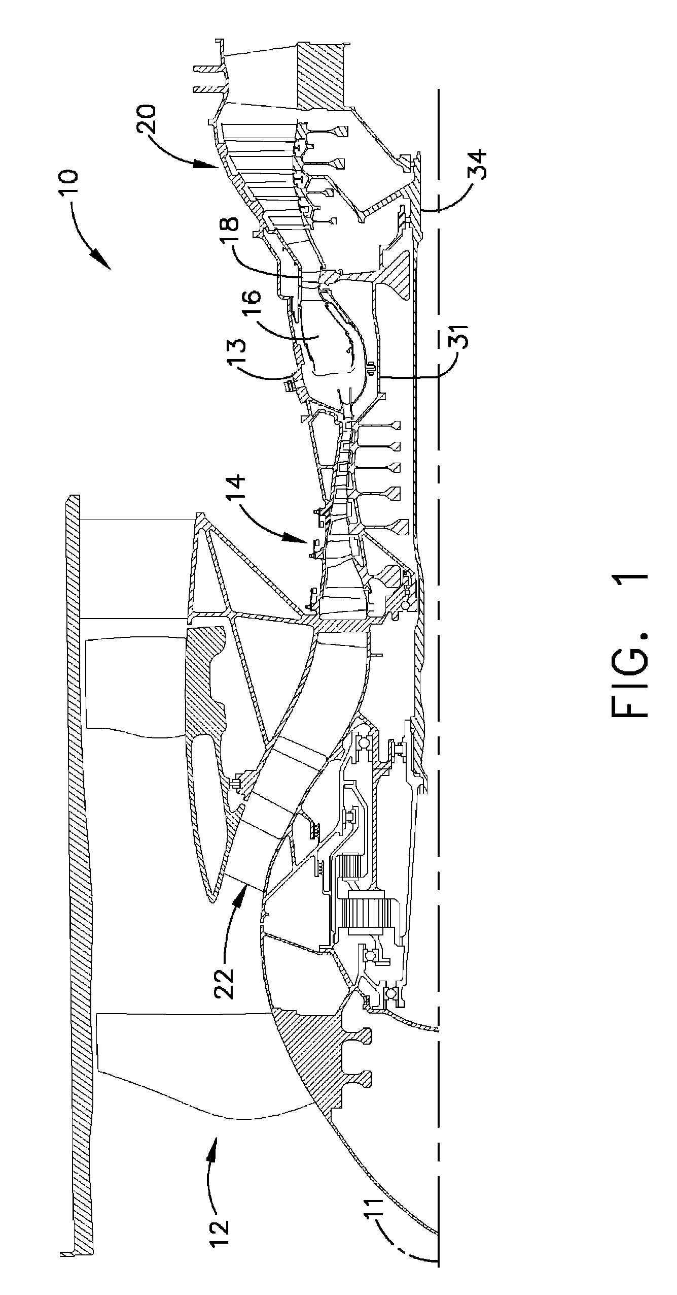
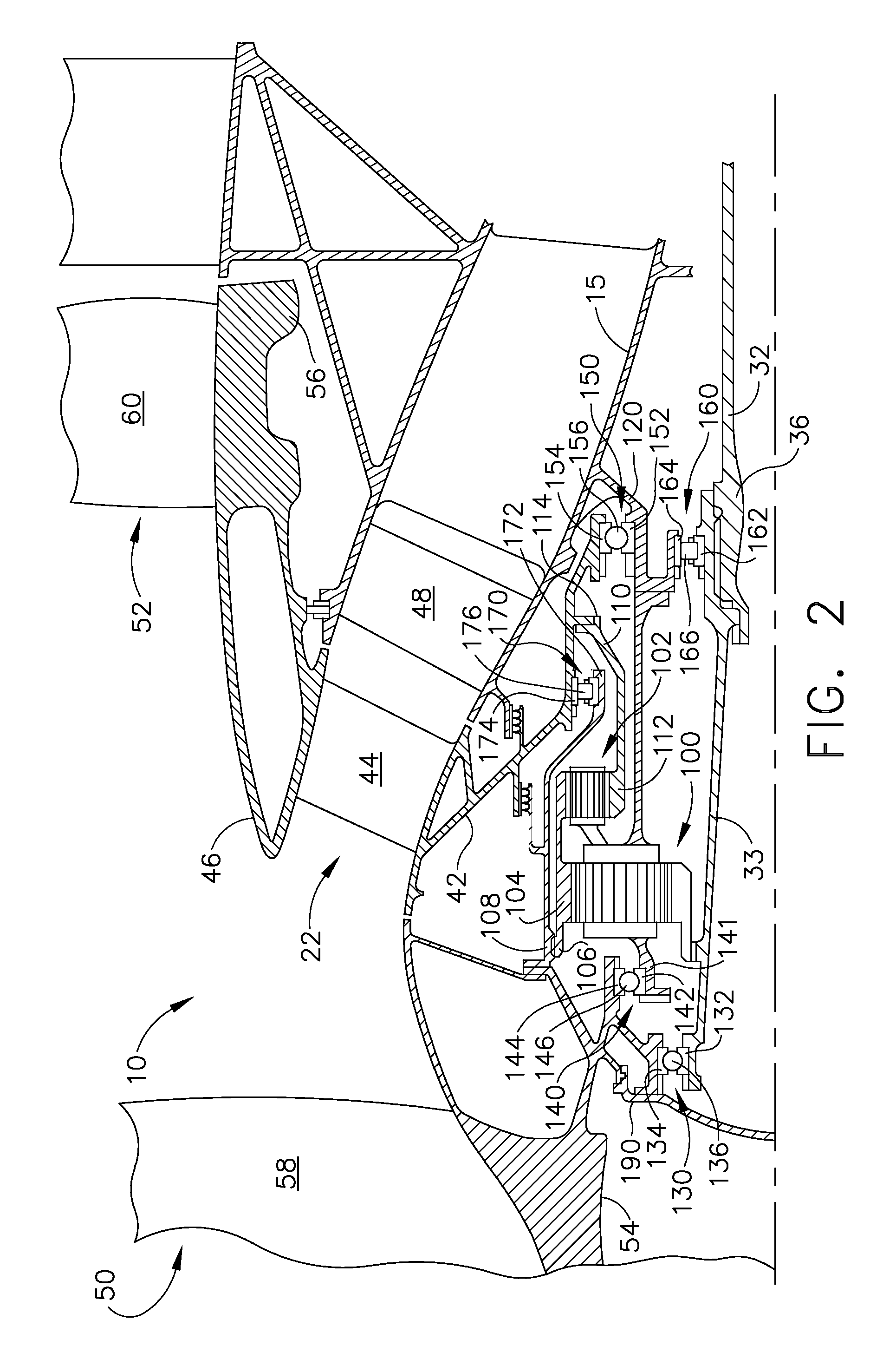
[0008]FIG. 1 is a schematic illustration of an exemplary turbofan engine assembly 10 having a longitudinal axis 11. Turbofan engine assembly 10 includes a fan assembly 12, a core gas turbine engine 13 that is disposed downstream from fan assembly 12, and a single-rotation low-pressure turbine 20 that is disposed downstream from the core gas turbine engine. The core gas turbine engine includes a high-pressure compressor 14, a combustor 16, a high-pressure turbine 18, and a first drive shaft 31 that is coupled between high-pressure compressor 14 and high-pressure turbine 18. In the exemplary embodiment, turbofan engine assembly 10 also includes a multi-stage counter-rotating booster compressor 22 that is disposed downstream from fan assembly 12 and upstream from core gas turbine engine 13. Turbofan engine assembly 10 also include a second drive shaft 32 that includes a first end 34 that is coupled or splined to low-pressure turbine 20 and a second end 36 that is coupled or splined to ...


PUM

PropertyMeasurementUnit
pressureaaaaaaaaaa
rotational speedaaaaaaaaaa
pressure balanceaaaaaaaaaa

Abstract

A turbofan engine assembly includes a core gas turbine engine including a high-pressure compressor, a combustor, and a high-pressure turbine, a first fan assembly disposed upstream from the core gas turbine engine, a first gearbox coupled to the first fan assembly, and a second gearbox coupled to a booster compressor such that the booster compressor rotates in a rotational direction that is opposite to the rotational direction of the first fan assembly. A method of assembling the above turbofan engine assembly is also described herein.

Description

BACKGROUND OF THE INVENTION[0001]This invention relates generally to gas turbine engines, and more specifically to a turbofan engine assembly that includes a counter-rotating booster compressor.[0002]At least some known turbofan engine assemblies include a fan assembly, a core gas turbine engine, and a low-pressure or power turbine. The core gas turbine engine includes at least one compressor, a combustor, and a high-pressure turbine that are coupled together in a serial flow relationship. Moreover, at least one known turbofan engine assembly includes a booster that is disposed between the fan assembly and the core gas turbine engine.[0003]To increase engine efficiency, at least one known turbofan engine assembly includes a counter-rotating low-pressure turbine that is coupled to a counter-rotating fan assembly. More specifically, to assemble a turbofan engine assembly that includes a counter-rotating low-pressure turbine, an outer rotating spool, a rotating frame, a mid-turbine fra...

Claims


Application Information

Patent Timeline
Patent Type & Authority Patents(United States)
IPC IPC(8): F02K3/06F02K3/072
CPCF02C3/107F02C7/36F02K3/072Y10T29/49236F05D2260/4031F05D2260/40311
Inventor SCHILLING, JAN CHRISTOPHER
Owner GENERAL ELECTRIC CO
Learn More