Eureka AIR delivers breakthrough ideas for toughest innovation challenges, trusted by R&D personnel around the world.

Airflow deflector assembly

a technology of airflow and deflector, which is applied in the direction of roofs, transportation and packaging, vehicle arrangements, etc., can solve the problems of reducing fuel efficiency of yaw, and achieve the effects of convenient removal, quick and easy installation, and facilitate the aforementioned sliding engagemen

Inactive Publication Date: 2011-02-01
EMBLER SUSAN +2
View PDF37 Cites 7 Cited by
  • Summary
  • Abstract
  • Description
  • Claims
  • Application Information

AI Technical Summary

Benefits of technology

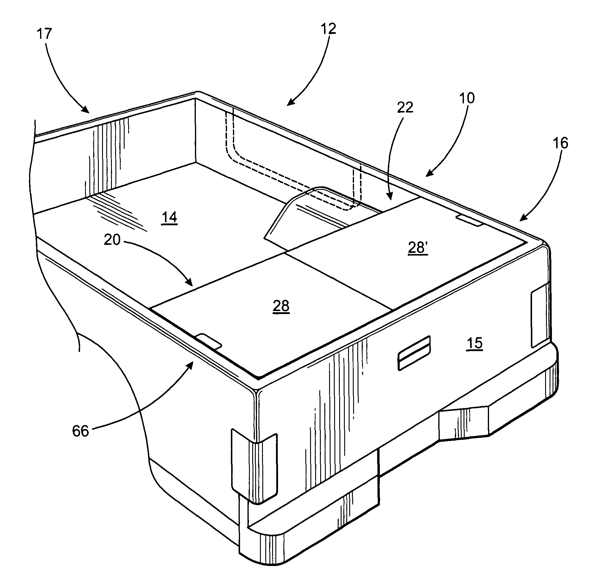
"The present invention is an airflow deflector assembly for vehicles with an open bed, such as pick-up trucks. The assembly consists of multiple cover sections that can be positioned in different orientations to increase the aerodynamic performance of the vehicle. The cover sections can be adjusted to cover the entire width of the bed or just a portion of it. The assembly is easy to install and remove, and can be adjusted for different vehicle sizes. The cover sections are designed to reduce air drag, improve fuel economy, and improve traction. The assembly includes attachment legs that allow for easy positioning and interconnection of the cover sections. The cover sections can be moved relative to each other to achieve different operative orientations. The airflow deflector assembly is effective in any pick-up truck with an open bed and can be used with other vehicles as well."

Problems solved by technology

More in particular, mounting the present airflow deflector assembly proximate the rearmost portion of the bed of a pick-up truck, such that the forward portion of the bed is left open, significantly improves the aerodynamics and reduces the yaw resulting from crosswinds and, as noted above, yaw is known to reduce fuel efficiency.

Method used


Image

  • Airflow deflector assembly
  • Airflow deflector assembly
  • Airflow deflector assembly

Examples


Embodiment Construction

[0071]As represented in the accompanying drawings, the present invention is directed to an airflow deflector assembly generally indicated as 10. The structural and operational features of the airflow deflector assembly 10 are such as to facilitate it being quickly, easily, and removably mounted or connected to a vehicle 12 in any one of a plurality of operative orientations, at least two of which are represented in FIGS. 1 and 2. The various operative orientations, as described in greater detail hereinafter, are such as to accommodate different sizes of an open bed 14 of the vehicle 12. More specifically, when in any of the aforementioned plurality of operative orientations, the airflow deflector assembly 10 will be disposed in overlying, covering relation to the trailing end 16 of the open bed 14 of the vehicle 12. As such, the trailing end 16 is represented as being immediately adjacent to and extending forwardly of the tailgate 15 of the vehicle 12. However, the preferred locatio...


PUM


Abstract

An airflow deflector assembly for an open bed truck or like vehicle including a plurality of preferably two cover sections each having a base and an attachment assembly cooperatively disposed and structured to adjustably interconnect the two cover sections facilitating their selective positioning into any one of a plurality of operative orientations. The selected operative orientation corresponds to the width of the trailing end of the open bed of the vehicle so as to so as to establish a substantially continuous air deflecting surface over the trailing end and thereby increasing the aerodynamics of the vehicle. The cooperative structuring of the attachment assemblies facilitate an adjustable sliding interconnection there between such that the bases of each cover section may be reciprocally positioned toward and away from one another to assume the preferred operative orientation corresponding to the width of the truck bed.

Description

CLAIM OF PRIORITY[0001]The present application is a continuation-in-part application of the previously filed and currently U.S. patent application having Ser. No. 11 / 999,571, filed on Dec. 7, 2007 now U.S. Pat. No. 7,566,093, which claims priority pursuant to 35 U.S.C. Section 119 to the provisional patent application having Ser. No. 60 / 873,339 and a filing date of Dec. 8, 2006, both of which are incorporated herein in their entirety by reference.BACKGROUND OF THE INVENTION[0002]1. Field of the Invention[0003]This invention is directed to an airflow deflector assembly removably positioned in covering relation to the trailing end of an open bed of a pick-up truck or like vehicle thereby improving the aerodynamics of the vehicle, reducing air drag and increasing fuel economy. The airflow deflector assembly comprises an air deflecting surface at least partially defined by a plurality of at least two cover sections adjustably interconnected to assume any one of a plurality of operative ...

Claims


Application Information

Patent Timeline
Patent Type & Authority Patents(United States)
IPC IPC(8): B60J7/00
CPCB62D33/0273B62D35/001B62D35/007Y02T10/82
Inventor EMBLER, SUSANEMBLER, KENNETHEMBLER, MARK
Owner EMBLER SUSAN
Why Eureka
Eureka Blog
Learn More