Controlling vibrations

a technology of vibration and control, applied in the direction of shock absorbers, instruments, static/dynamic balance measurement, etc., can solve the problems of not providing a mounting device in which there was active imposition of vibrations to counter the vibrations applied to the mounting device, changing both vibration amplitude and phase, and what might appear to be the correct phase of a cancellation signal at one point in the structure may well be detrimental at another poin

Active Publication Date: 2011-02-01
DN AUTOMOTIVE CORP
View PDF18 Cites 0 Cited by
  • Summary
  • Abstract
  • Description
  • Claims
  • Application Information

AI Technical Summary

Benefits of technology

[0030]In GB-A-2354054, it was assumed that the intention of the active control of the mounting device was to generate vibrations within the mounting device which would cancel the vibrations applied to the mounting device. This would eliminate, or at least significantly reduce, transmission of vibrations via the mounting device.
[0031]However, it has been realised that, at least for aesthetic purposes, it is sometimes desirable to apply a vibration which is not the same as the vibration input. Consider an engine vibrating in a vehicle. The techniques discussed above, and in GB-A2354054, it may be possible to control the chassis so as substantially to eliminate the vibrations of the engine which are transmitted to the chassis. This eliminates the vibrations that are transmitted to the driver and passengers since the vibrations of the engine are not transmitted via the chassis to the driver and passengers, and the chassis does not vibrate to generate sounds which would be transmitted to the driver and passenger. However, it is not always desirable wholly to eliminate such transmissive or audio vibrations. Some help driver control, and other sounds may be seen as desirable. For example, the driver of a vehicle with a four cylinder engine may want to hear the sounds associated with a more powerful 6 or 8 cylinder engine.
[0043]In this aspect it is preferable, but not essential, that the control of the mounting device also suppresses unwanted vibrations, in a manner similar to the arrangements discussed with reference to the first aspect, or as in GB-A-2354054. In this development, the mounting device may be controlled to generate a variable force to oppose the vibrations, but that variable force is modified to generate the force at the frequency corresponding to the harmonic desired. Thus, for example, vibrations at twice engine speed, which are perceived as undesirable because they make the engine appear unrefined, may be reduced or eliminated, and a harmonic or harmonics associated with more refined engines imposed, e.g. at three or four times engine speed.

Problems solved by technology

This provided a “semi-active” mount, but still did not provide a mounting device in which there was active imposition of vibrations to counter the vibrations applied to the mounting device.
The main problem in achieving this is that generally structural components, through which the vibrations pass, tend to change both the vibration amplitude and phase.
This means that what might appear to be the correct phase of a cancellation signal at one point in the structure may well be detrimental at another.

Method used


Image

  • Controlling vibrations
  • Controlling vibrations
  • Controlling vibrations

Examples


Embodiment Construction

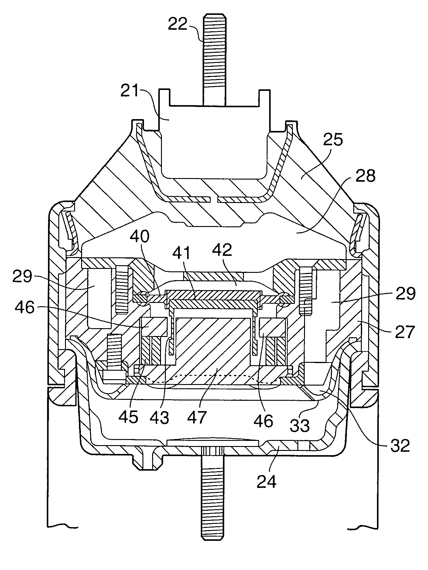
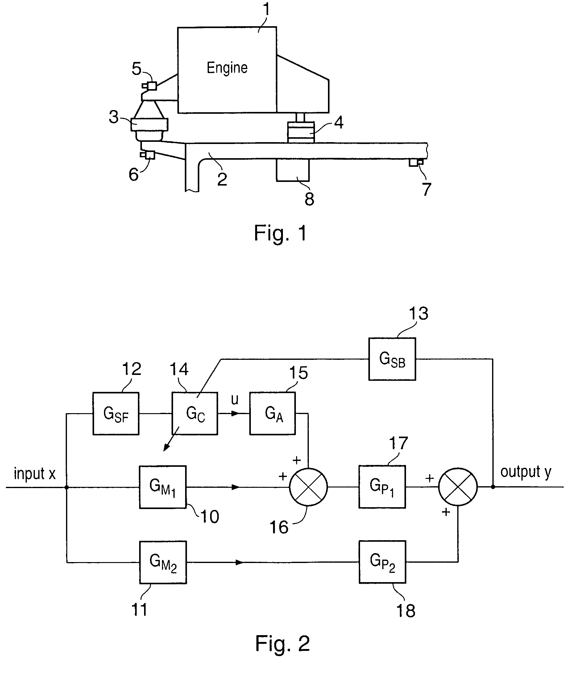
[0073]Referring first to FIG. 1, an automobile engine 1 is mounted on a chassis 2 via a mounting device 3 which, as will be described in more detail later, provides active damping of the vibrations of the engine 1 relative to the chassis 2. The engine 1 may also be connected to the chassis 2 via other mounting devices 4 which do not provide such active damping. A feed-forward sensor 5, which may be e.g. an accelerometer, senses the input vibrations applied to the mounting device 3 from the engine 1, and a feed-back sensor 6 senses the vibrations which are transmitted to the chassis 2 via the mounting device 3.

[0074]The mounting device 3 can be considered to have two elements, namely a passive damping element, and an actuator element operating in parallel to the passive element. A control system senses the vibrations from the engine 1 via the sensor 5, and controls the actuator of the mount 3 with the intention of minimising the output sensed by the sensor 6. The outputs of the senso...


PUM


Abstract

In order to control vibrations of two parts of a piece of machinery, a variable force may be generated to oppose the vibrations, with the variable force being generated under control of a controller on the basis of an iterative relationship, the iterative relationship being such as to generate the force of one iteration using a controller output signal in frequency domain vector form derived from the controller output signal of the immediately previous iteration in frequency domain vector form plus a frequency domain vector quantity derived from the resultant vibration of more than one previous iteration.Where these two parts are connected by multiple (f) mounting devices, the controller output signals a previous iterations are taken into account, and the frequency domain vector quantity derived from the controller output signals and more than f previous iterations.The information corresponding to the vibration frequency may be derived from a rotating shaft, where the two parts are the engine and chassis of a vehicle.It is also possible generate a force between the two parts which is a harmonic of the frequency of vibration being suppressed.

Description

BACKGROUND OF THE INVENTION[0001]1. Field of the Invention[0002]The present invention relates to the control of vibrations. It is particularly, but not exclusively, concerned with controlling vibrations in an automobile, such as vibrations between the engine and its mounting.[0003]2. Summary of the Prior Art[0004]EP-A-0115417 and EP-A-0172700 discussed two different types of hydraulically damped mounting devices for damping vibration between two parts of a piece of machinery, e.g. a car engine and a chassis. EP-A-0115417 disclosed various “cup and boss” type of mounting devices, in which a “boss”, forming one anchor part to which one of the pieces of machinery was connected, was itself connected via a deformable (normally resilient) wall to the mouth of a “cup”, which was attached to the other piece of machinery and formed another anchor part.[0005]The cup and the resilient wall then defined a working chamber for hydraulic fluid, which was connected to a compensation chamber by a pa...

Claims


Application Information

Patent Timeline
Patent Type & Authority Patents(United States)
IPC IPC(8): F16F13/00F16M13/00F16F13/26G05D19/02
CPCG05D19/02F16F13/266F16F13/26F16F15/027
Inventor FURSDON, PETER MICHAEL TREWHELLA
Owner DN AUTOMOTIVE CORP
Why Eureka
Try Eureka