
Dual control line system and method for operating surface controlled sub-surface safety valve in a well

a safety valve and sub-surface technology, applied in the direction of fluid removal, sealing/packing, borehole/well accessories, etc., can solve the problem of redundancy in the control of the safety valve, and achieve the effect of reducing debris and contamination

Active Publication Date: 2011-02-01
WEATHERFORD TECH HLDG LLC
View PDF9 Cites 11 Cited by
  • Summary
  • Abstract
  • Description
  • Claims
  • Application Information

AI Technical Summary

Benefits of technology

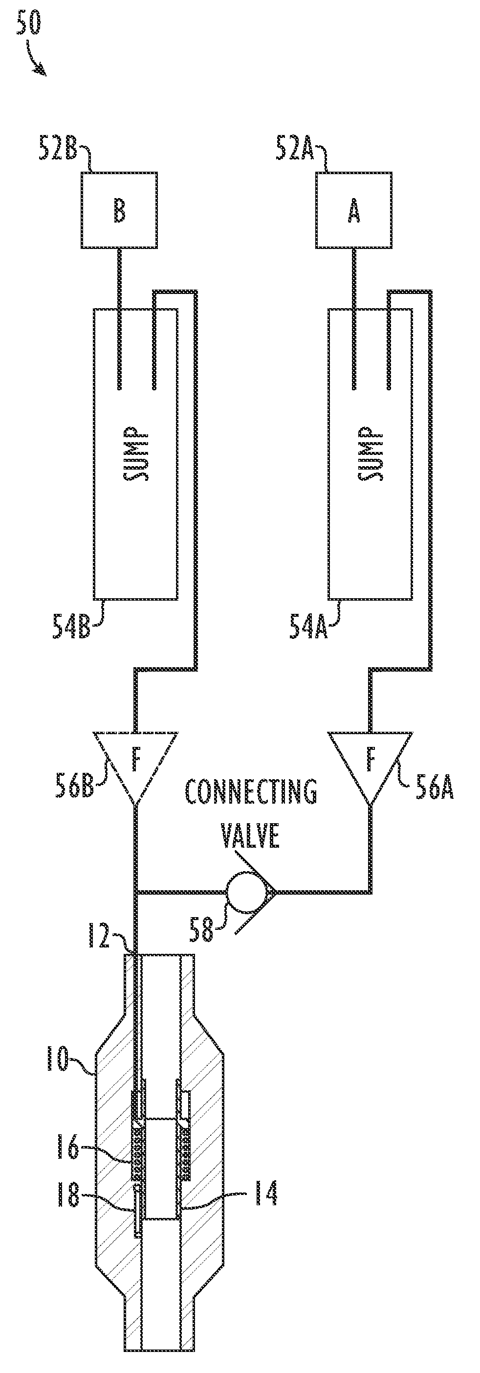
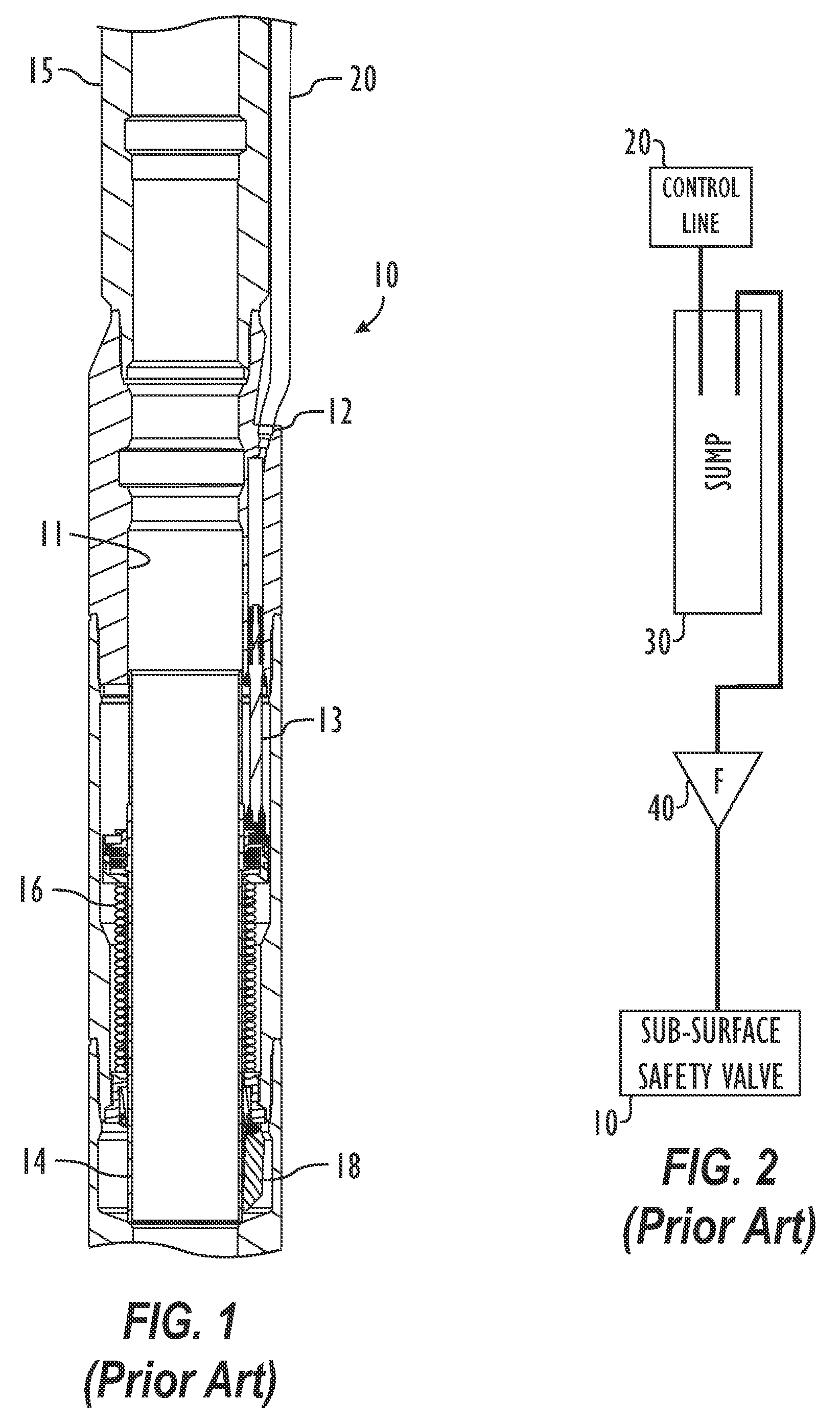
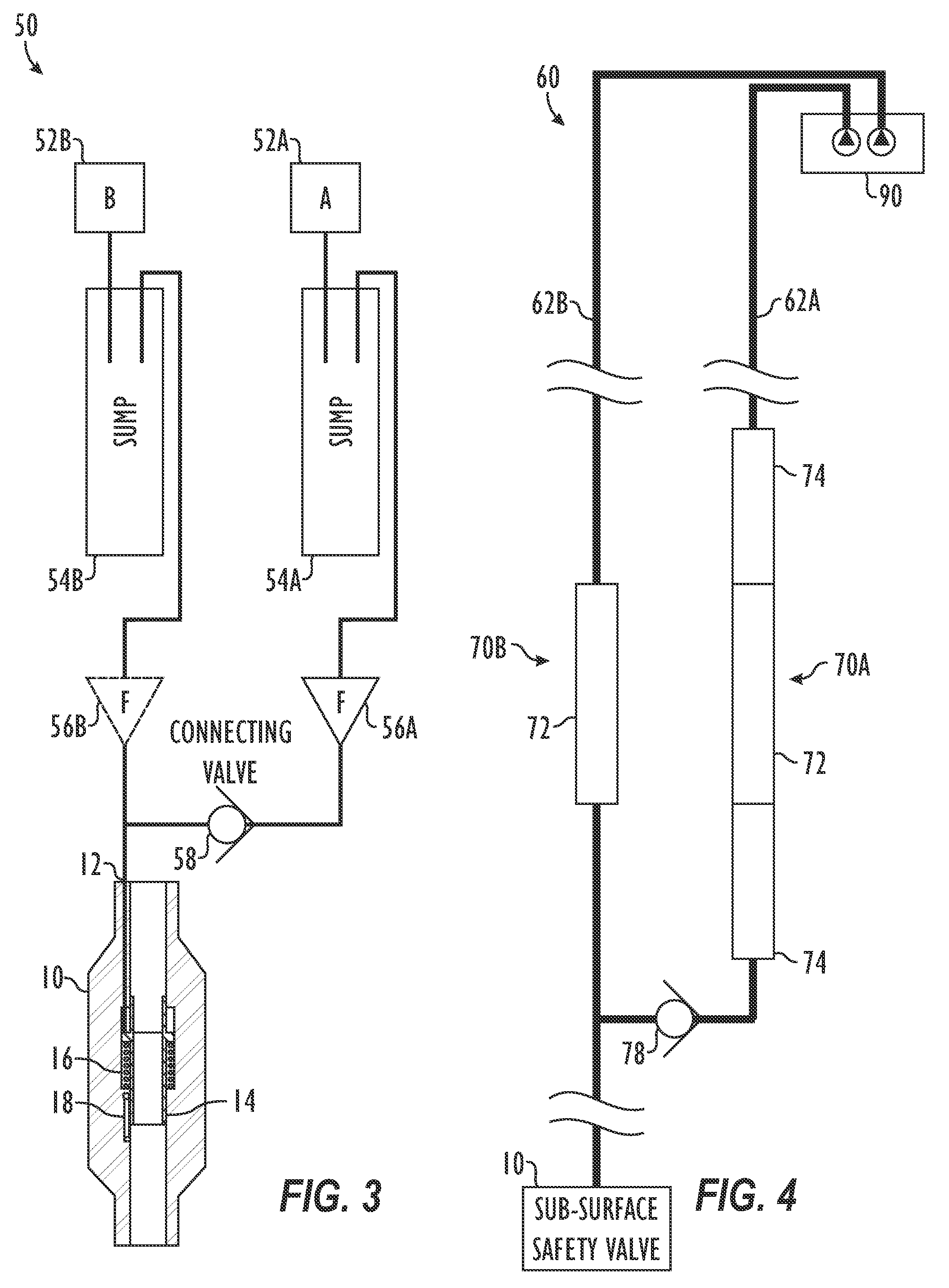
[0007]A dual control line system is used for a surface controlled sub-surface safety valve. In the dual control line system, first and second control lines communicate control fluid to the same control port of the sub-surface safety valve. The first control line preferably has a sump component to collect debris from the control fluid and has one or more in-line filters to filter debris from the control fluid. Preferably, the second control line also has a sump component to collect debris but may not have any in-line filters in one embodiment. A connecting valve is connected between the first and second control lines. The connecting valve allows control fluid to communicate from the first control line to the safety valve but prevents fluid communication from the second control line to the first control line. To open the valve, a well control panel applies hydraulic pressure to the safety valve via the first control line. To close the valve, the well control panel exhausts the hydraulic pressure to a reservoir via the second control line. Use of the dual control lines, sumps, and filters allows control fluid to migrate through the system and can reduce the debris and contamination in the control fluid. In addition, the dual control line system can be cycled to remove debris from the system. Furthermore, the dual control lines provide redundant control of the safety valve if one of the control lines becomes blocked or damage.

Problems solved by technology

Furthermore, the dual control lines provide redundant control of the safety valve if one of the control lines becomes blocked or damage.

Method used


Image

  • Dual control line system and method for operating surface controlled sub-surface safety valve in a well
  • Dual control line system and method for operating surface controlled sub-surface safety valve in a well
  • Dual control line system and method for operating surface controlled sub-surface safety valve in a well

Examples


Embodiment Construction

[0016]FIG. 3 illustrates one embodiment of a dual control line system 50 for a surface controlled sub-surface safety valve (“safety valve”) 10. The system 50 includes first and second control lines 52A-B interconnected to one another by a one-way connecting valve 58 and connected to a single control port 12 of the safety valve 10. With the two control lines 52A and 52B run from the surface to the safety valve 10, one of the control lines 52A can power the safety valve 10 open while the second control line 52B can be used to close the valve 10.

[0017]In particular, the first control line 52A is the main line used to power the safety valve 10 hydraulically to the open position. To open the valve, for example, a wellhead control panel (not shown) at the surface applies hydraulic pressure to the control port 12 via control fluid in the first control line 52A. The well control panel can include any conventional device at the surface used to operate a sub-surface safety valve or the like v...


PUM


Abstract

A control system for a surface controlled sub-surface safety valve has first and second control lines. The first control line communicates control fluid to the sub-surface safety valve and preferably has a sump and in-line filters. Hydraulic pressure applied to the safety valve with this first control line can open the safety valve. The second control line also communicates control fluid to the sub-surface safety valve and preferably has a sump. A connecting valve is connected between the first and second control lines. The connecting valve allows control fluid to communicate from the first control line to the safety valve but prevents fluid communication from the second control line to the first control line. To open the valve, the second control line is exhausted to a reservoir. The dual control lines provide redundant control of the safety valve and can also be cycled to remove debris from the system.

Description

FIELD OF THE DISCLOSURE[0001]The subject matter of the present disclosure generally relates to a surface controlled sub-surface safety valve for a well and, more particularly, to a dual control line system for communicating control fluid to a sub-surface safety valve that is remotely controlled from the surface and that has a single line input for the control fluid.BACKGROUND OF THE DISCLOSURE[0002]In an oil and gas well, a sub-surface safety valve is a downhole valve normally maintained in an open position to allow fluid to flow through the valve. The safety valve is closed to prevent blowout of the well, for example, if an excessive pressure drop or flow occurs across the safety valve. One type of sub-surface safety valve uses a spring and choke mechanism to close the valve if the well flow rate exceeds a predetermined level. Another type uses a pre-charged chamber to close the valve if the pressure caused by increased flow falls below a predetermined value.[0003]Yet another type ...

Claims


Application Information

Patent Timeline
Patent Type & Authority Patents(United States)
IPC IPC(8): E21B34/10
CPCE21B34/10E21B41/00
Inventor SMITH, RODDIE R.JONES, RICHARD C.DENNISTOUN, STUART M.
Owner WEATHERFORD TECH HLDG LLC
Learn More