
Audio apparatus having tuner unit and digital reproducing unit

a technology of digital reproduction and audio equipment, which is applied in the field of audio equipment, can solve the problems of determining the location of the new switch and the increase in the cost, and achieve the elimination of the problem of installing any additional new keys, preventing the interference of the radio frequency noise component of the cd player, and reducing the cos

Inactive Publication Date: 2011-01-25
SONY CORP
View PDF7 Cites 1 Cited by
  • Summary
  • Abstract
  • Description
  • Claims
  • Application Information

AI Technical Summary

Benefits of technology

The present invention provides an audio apparatus with a tuner unit, digital reproducing unit, and control unit that can switch between different modes based on the input from the user. In the first mode, the control unit controls the tuner unit and digital reproducing unit, turning on the power of the digital reproducing unit when an audio signal is received. In the second mode, the control unit controls the tuner unit and digital reproducing unit, turning off the power of the digital reproducing unit when an audio signal is received, and then turning it on again when selecting the audio signal outputted from the digital reproducing unit. This allows for quick switching between different audio sources without interfering with the system stereo. The control unit also controls the power of the CD player based on the CD power flag, ensuring that the CD player is always ready to play a CD. The system stereo also eliminates the need for additional keys and reduces the likelihood of erroneous operation. The present invention is also applicable to other digital reproducing units that may interfere with FM or TV broadcasting.

Problems solved by technology

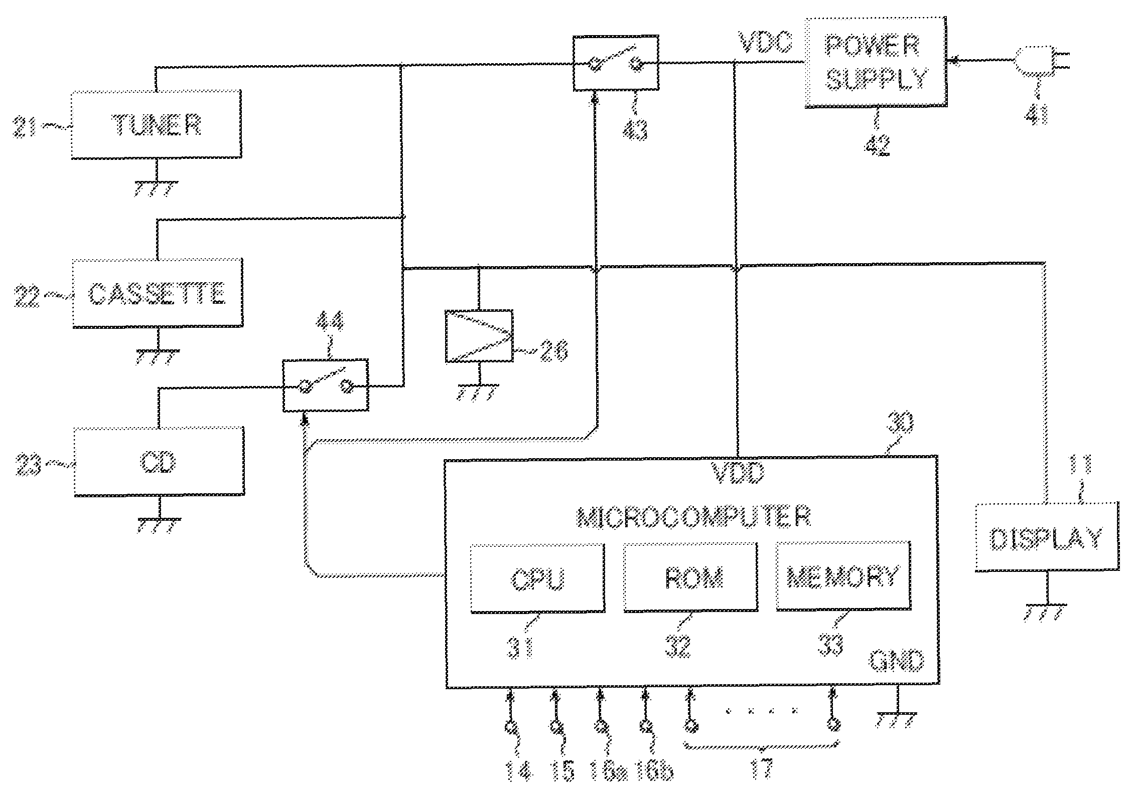
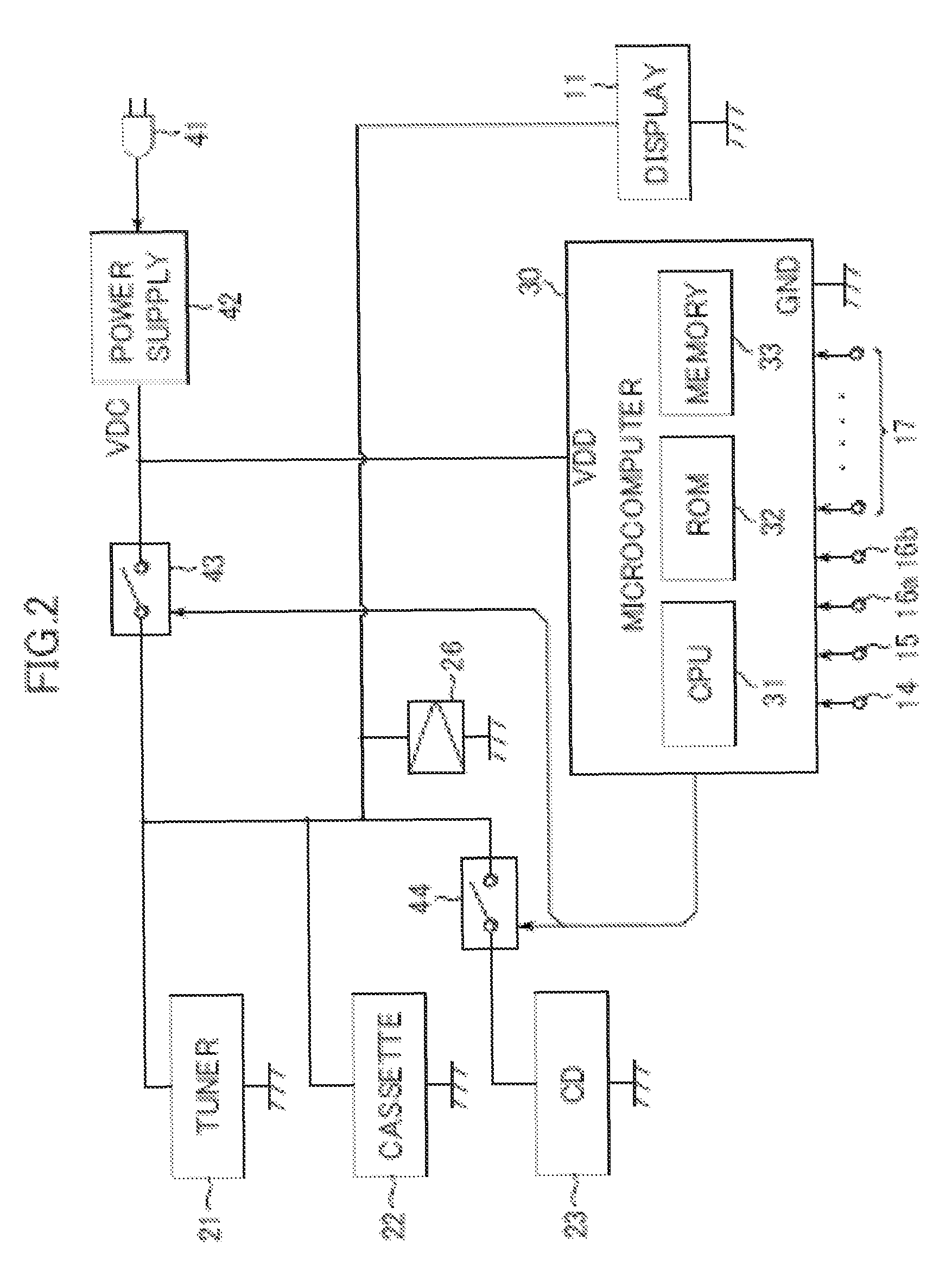
Further, in a case where a new switch for switching the CD power flag “CDPWRF” is to be provided, it incurs an increase in the cost and a problem in determining where the new switch is to be installed.

Method used


Image

  • Audio apparatus having tuner unit and digital reproducing unit
  • Audio apparatus having tuner unit and digital reproducing unit
  • Audio apparatus having tuner unit and digital reproducing unit

Examples


Embodiment Construction

[0031]At first, configuration of an audio signal circuitry and its basic operations of the invention is described.

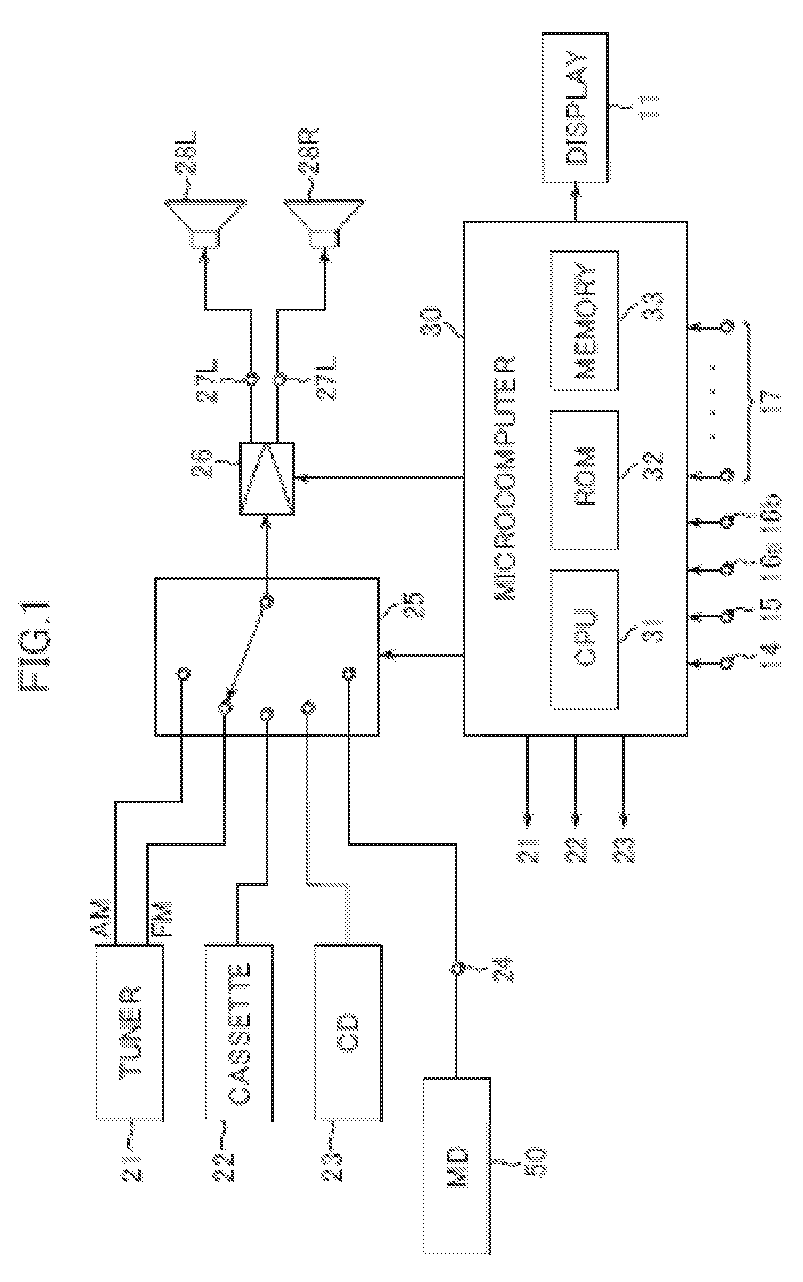
[0032]FIG. 1 is a schematic diagram showing an audio signal circuitry in a system stereo according to an exemplary embodiment of the present invention. This exemplary embodiment specifies such one operable on AM / FM broadcasting, a CD and a cassette as its source, and, in addition, an MD recording / reproducing unit which is optionally connected. An appearance thereof as viewed from its front is given in FIG. 6.

[0033]By referring to FIG. 1, this system stereo has, as its sources, an AM / FM tuner 21, a cassette tape deck 22, a CD player 23, and a line input terminal 24. In this embodiment, the AM / FM tuner 21 which is a synthesizer type tuner and has a microcomputer (not shown) for control of reception, is constructed to be able to change a receiving band and a receiving frequency freely in response to a command accompanying data sent from a microcomputer 30 for use in a syste...


PUM

PropertyMeasurementUnit
poweraaaaaaaaaa
currentaaaaaaaaaa
volumeaaaaaaaaaa

Abstract

An audio apparatus comprises a tuner for receiving broadcast waves; a digital reproducing unit; operation switches for operating the tuner and the digital reproducing unit; and a control unit for controlling the tuner and the digital reproducing unit in response to an operation of the operation means. In a first mode of operation, the control unit controls if an audio signal from the tuner is selected as a source such that the power of the digital reproducing unit is turned on, and wherein, in a second mode operation, the control unit controls if an audio signal from the tuner is selected as a source such that the power of the digital reproducing unit is turned off, alternatively if an audio signal from the digital reproducing unit is selected as a source, the power thereof is turned on.

Description

RELATED APPLICATION DATA[0001]The present application claims priority to Japanese Application(s) No(s). P2003-092330 filed Mar. 28, 2003, and P2004-038488 filed Feb. 16, 2004, which application(s) is / are incorporated herein by reference to the extent permitted by law.BACKGROUND OF THE INVENTION[0002]1. Field of the Invention[0003]The present invention relates to an audio apparatus, and in particular, to an audio apparatus including a tuner unit and a digital reproducing unit.[0004]2. Description of the Related Art[0005]As a consumer-use audio apparatus, there is a so-called system stereo. This system stereo, for example, is comprised of an AM-FM tuner, recording / reproducing components such as a cassette tape recorder, a compact disc (CD) player, a mini disc (MD) recorder / player and the like, and they are integrated and housed in a single cabinet.[0006]FIG. 6 is a frontal view showing one example of a specific appearance of such system stereo. This system stereo in this example can h...

Claims


Application Information

Patent Timeline
Patent Type & Authority Patents(United States)
IPC IPC(8): H02B1/00H04R29/00H04B1/00H04B1/10H04B1/16H04B1/06H05K11/00G11B31/00G11B33/10H04B1/20H04B15/02
CPCH04B1/20H04B15/02C02F1/50B01D35/30B01D35/02D06F39/10E03D9/08B01D2201/4092
Inventor TANAKA, YOZOOTSU, MASAHIROOOSUKA, HIROTAKAMIZUKI, MASAYUKI
Owner SONY CORP
Learn More