
Washing container

a technology for washing containers and washing dishes, applied in the field of dishwashing machines, can solve the problems of clogging or overfilling of the sieve plate, affecting so as to reduce the risk of overfilling the effect of heavy lifting of the covering sieve and reducing the use of household appliances

Active Publication Date: 2011-01-25
MEIKO MASCHENBAU
View PDF6 Cites 0 Cited by
  • Summary
  • Abstract
  • Description
  • Claims
  • Application Information

AI Technical Summary

Benefits of technology

[0012]The present invention is based on the object of firstly avoiding the disadvantages of the solutions known from the prior art and of secondly providing a solution with which machine entry points can be continuously cleaned from food residues and the use of covering sieves, in particular of large design, can be completely omitted.
[0017]In order to fill the water or washing container, washing water can be used from any desired tank of the conveyor-type dishwasher, whether the tank in the preliminary cleaning zone, whether a tank within the washing zone, whether a pump-operated final-rinsing tank, or whether fresh water is used. If fresh water is used, a better cleaning effect can advantageously be obtained.
[0019]The water container used as the washing container is preferably designed in such a manner that it is open toward its upper side in order to also discharge the quantity of water which produces the water film in the manner of a gush of water from the container. If a plurality of water containers used as washing containers are inserted at a machine entry point, the water containers may differ in shape and size in order to produce different washing-away times and different quantities of water and therefore water films of differing energy. The shape of the water container used as a washing container may be asymmetrical or symmetrical. If the water container used as the washing container is of symmetrical design, the advantage arises that said water container, for example after being removed for cleaning, can be inserted again into the entry region in its correct fitted position.
[0020]The water container used as the washing container is fitted in such a manner that it can be removed in a simple manner with just a few actions and can be cleaned in a simple manner. With the emptying of the filled water container serving as the washing container, large food residues, papers, serviettes or other waste can be washed away, and therefore no covering sieves whatsoever are required in the machine entry region of the solution proposed according to the invention. The removal and cleaning of the covering sieves and the soiling, necessitated by the cleaning of the covering sieves, of the kitchen region in which the automatic conveyor-type dishwasher is erected are therefore not needed. Furthermore, staff costs are reduced, since the implemented cleaning of the entry region means that the cleaning thereof at the end of the operation can be dispensed with, as can possible down times of the machine. In comparison to the production costs of previously used covering sieves, the production costs for the water container which is proposed according to the invention and serves as a washing container are low. In an alternative embodiment, it is possible to use the entry region cleaning proposed according to the invention and having at least one water container serving as a washing-away container in combination with a nozzle producing a water film. The degree of soiling of the machine entry point decreases by means of the solution proposed according to the invention, and therefore the previous outlay on cleaning can be considerably reduced.

Problems solved by technology

Said collecting container is connected to a discharge pipe and has a level limitation for the washing water.
The covering sieves are to be regularly emptied and cleaned, since otherwise there is a risk of the sieve plate becoming clogged or the covering sieves becoming overfilled.
The removal of the covering sieves which are partially or completely filled with dirt and are therefore heavy is not user-friendly for ergonomic reasons.
In order to clean the heavy covering sieves, the entire rinsing process has to be interrupted, depending on the location at which the covering sieves are used, and therefore the use of covering sieves and the cleaning, which is inevitably associated therewith, after the end of operation cause an additional expenditure of time and therefore additional costs.
However, this thin and therefore low-energy water film can only convey the smallest dirt fragments which pass through the sieves to the dirt-collecting sieve; larger dirt particles inevitably remain stuck to the trough base.
This necessitates the use of large covering sieves and has the disadvantage that large food residues cannot be conveyed in the direction of the dirt-collecting sieve by the only thin and low-energy water film which flows along the slightly inclined trough face.

Method used


Image

  • Washing container
  • Washing container
  • Washing container

Examples


Embodiment Construction

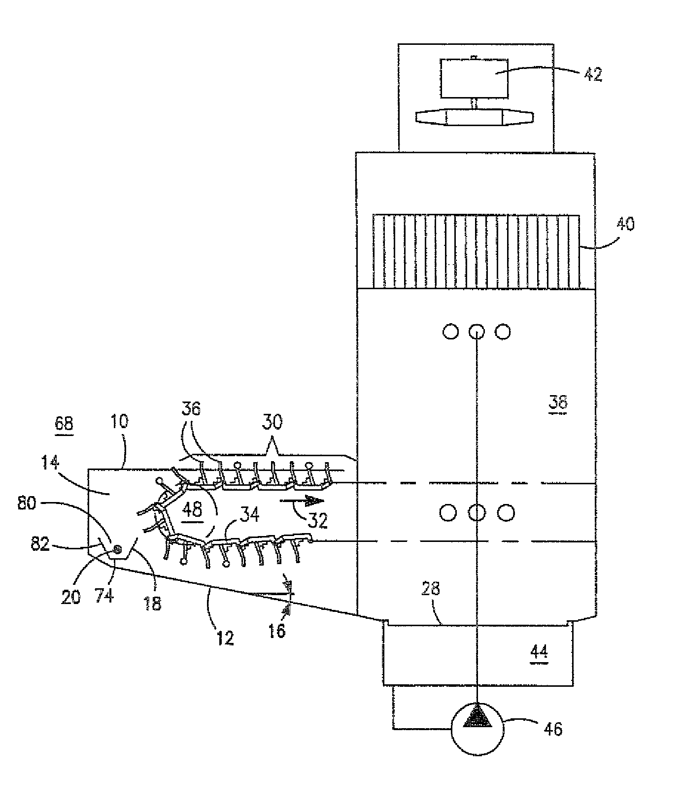
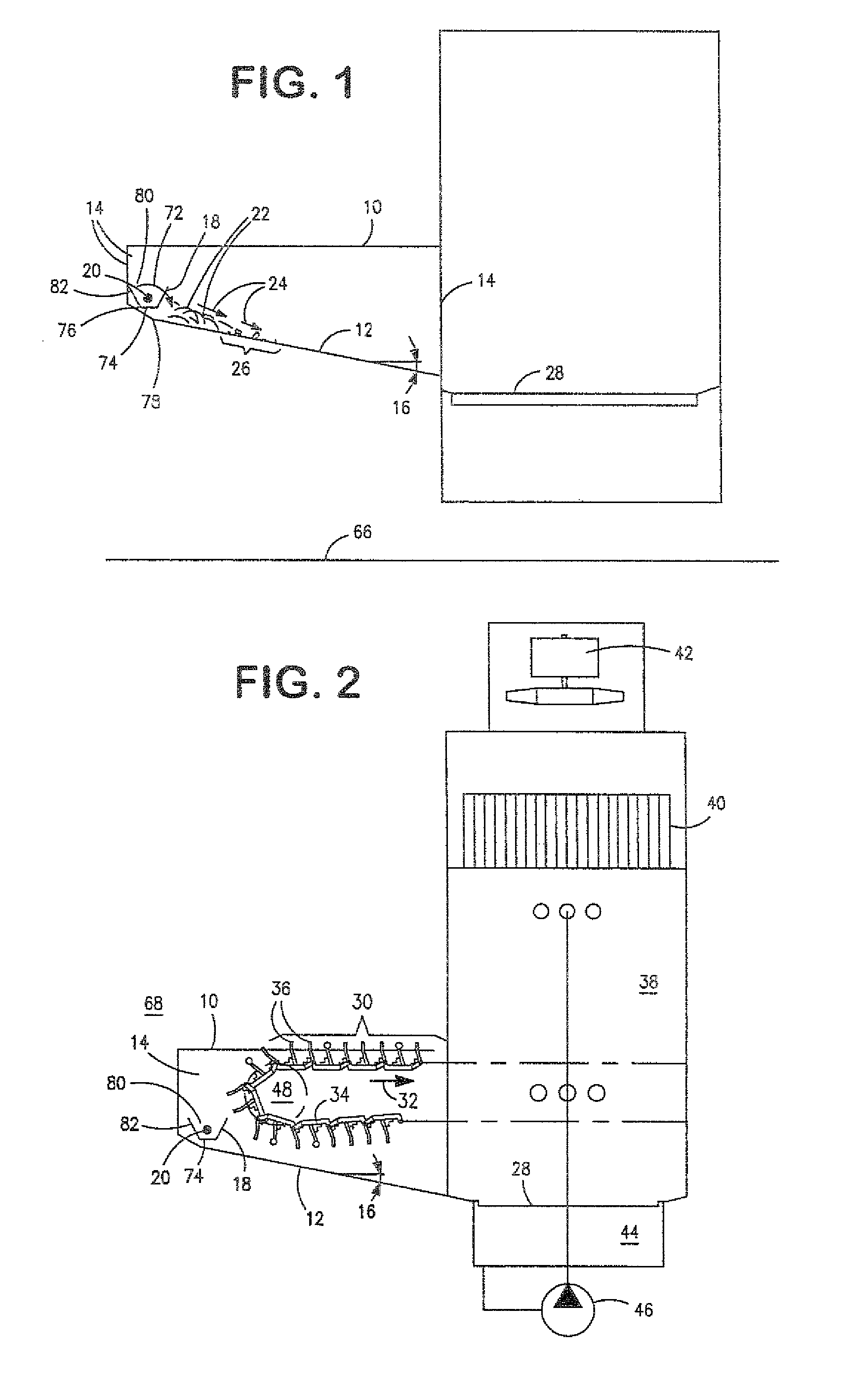
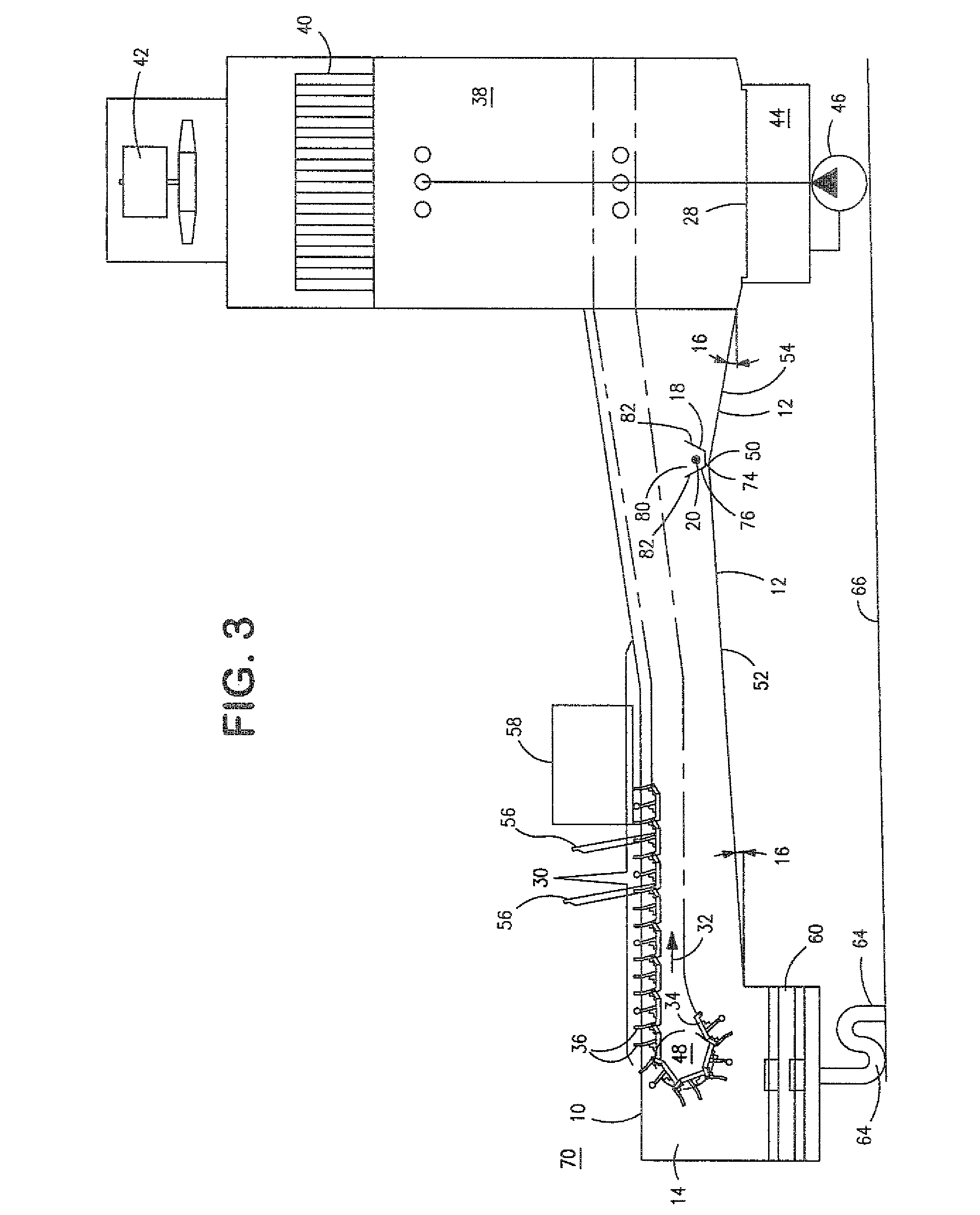
[0026]A first embodiment of the dishwasher entry region proposed according to the invention can be gathered from the illustration according to FIG. 1 which shows an entry region 10, in particular of a conveyor-type dishwasher, whether a basket transport machine or a conveyor-belt machine. In the illustration according to FIG. 1, an encircling transporting belt, on which either holding devices for receiving the items to be cleaned or holding devices for receiving baskets which, for their part, receive the items to be cleaned are provided, is not reproduced for reasons of better illustration.

[0027]The entry region 10 comprises a trough base 12 which, in the illustration, is designed with an incline or gradient 16 with respect to a dirt-collecting sieve 28. In the illustration according to FIG. 1, the trough base 12 runs with a continuous gradient 16. A gradient 16 which differs in degree, depending on the angle of inclination of the trough base 12, as indicated in FIG. 1, is produced ...


PUM


Abstract

The invention relates to an entry region of a conveyor-type dishwasher. A conveyor belt which moves in the conveying direction is located in the entry region. The entry region comprises a trough base which is bounded by sidewalls arranged laterally. The entry region contains at least one washing container which stores a stock of fluid and, upon emptying, cleans the trough base.

Description

CROSS REFERENCE TO RELATED APPLICATIONS[0001]This application is based on German Patent Application No. 10 2006 062 228.6 filed 22 Dec. 2006, upon which priority is claimed, and on Provisional Application 60 / 907,161 filed on Mar. 23, 2007.BACKGROUND OF THE INVENTION[0002]1. Field of the Invention[0003]The present invention relates to dishwashers, and more particularly to entry points of conveyor-type dishwashers, whether conveyor-belt machines or basket transport machines, with a trough-rinsing system integrated into the entry point.[0004]2. Prior Art[0005]DE 44 28 738 A1 discloses a conveyor-type dishwashing machine comprising a preliminary cleaning stage, a plurality of main rinsing stages and an after-rinsing stage. A heat exchanger which serves to recover heat is provided. In order to improve the access, the possibility of cleaning and the efficiency of the heat exchanger, the latter is arranged within the preliminary cleaning stage of the conveyor-type dishwashing machine under...

Claims


Application Information

Patent Timeline
Patent Type & Authority Patents(United States)
IPC IPC(8): B08B3/02
CPCA47L15/247
Inventor BREITSCHUH, AXEL
Owner MEIKO MASCHENBAU
Learn More