
Variation of neural stimulation parameters

a neural stimulation and parameter technology, applied in the field of neural stimulation parameter variation, can solve the problems of high artificial activity and non-physiologic pattern, 422 patent, and large drain on the battery of the implanted stimulator, and achieve the effect of minimizing the loss of therapeutic

Inactive Publication Date: 2011-01-18
MEDTRONIC INC
View PDF37 Cites 14 Cited by
  • Summary
  • Abstract
  • Description
  • Claims
  • Application Information

AI Technical Summary

Benefits of technology

[0011]An illustrative embodiment of the invention, overcomes the above-noted, and other, shortcomings of conventional neural stimulation devices. An illustrative embodiment of the invention provides techniques for varying stimulus parameters used in deep-brain stimulation (DBS) and other types of neural stimulation to minimize loss of therapeutic effectiveness due to physiologic tolerance to stimulation.
[0012]An illustrative embodiment of the invention includes a method of reducing the loss of therapeutic efficacy in neural stimulation due to development of physiologic tolerance to the stimulation. This method includes the steps of: providing neural stimulation that has multiple stimulation parameters including a stimulation amplitude, a stimulation frequency, a stimulation pulse duration, and a set of one or more electrode-polarity-firing conditions; pseudo-randomly varying at least a first of the stimulation parameters; and changing a value of a second stimulation parameter based upon having pseudo-randomly varied the first stimulation parameter and based upon a predetermined relationship that specifies how changes in the first parameter affect desirable values for the second parameter.

Problems solved by technology

Such a pattern of activity is highly artificial and non-physiologic compared to the recorded firing patterns of normal neurons.
The '422 patent, however, does not address the problem of development of a physiological tolerance to the stimulation.
For instance, obsessive-compulsive disorder is often treated with four electrodes placed in a specific brain structure, with each electrode stimulated at a relatively high current, which causes a large drain on an implanted stimulator's battery.
Similarly, it may not be possible to achieve the desired therapeutic effect without undesired side effects of stimulation when a large volume of tissue is simultaneously modulated.

Method used


Image

  • Variation of neural stimulation parameters
  • Variation of neural stimulation parameters
  • Variation of neural stimulation parameters

Examples


Embodiment Construction

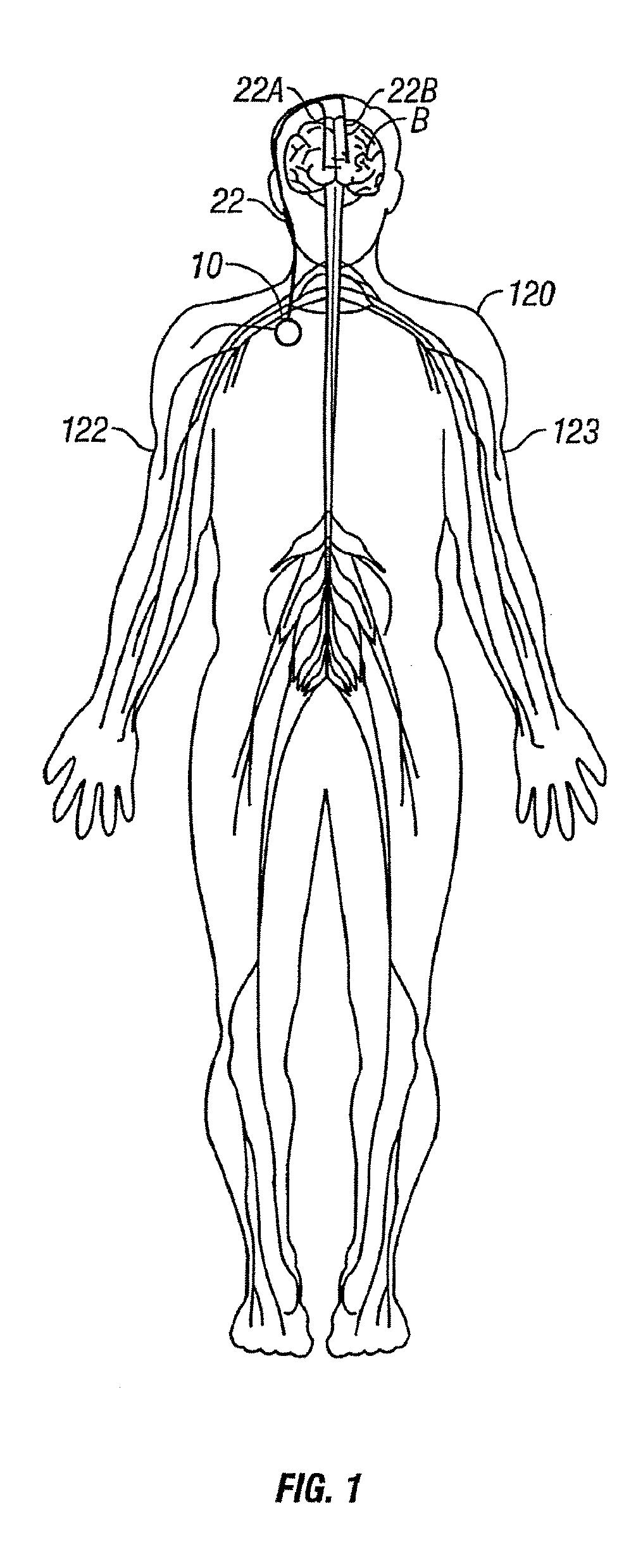
[0028]FIG. 1 depicts a microprocessor-controlled neural stimulation device 10 in accordance with an illustrative embodiment of the invention. Device 10 is preferably implanted below the skin of a patient, or alternatively, may be an external device. A lead 22A is positioned to stimulate a specific site in the brain (B). Device 10 may take the form of a modified signal generator Model 7424 manufactured by Medtronic, Inc. under the trademark Itrel II. Lead 22A may be any lead suitable for stimulation. The distal end of lead 22A terminates in one or more stimulation electrodes generally implanted into a portion of the brain such as the thalamus, the internal capsule, the globus pallidus, the subthalamic nucleus or other neural structure by conventional stereotactic surgical techniques. Any number of electrodes may be used for various applications. Each of the electrodes is individually connected to device 10 through lead 22A and conductor 22. Lead 22A is surgically implanted through a ...


PUM


Abstract

Techniques for varying stimulus parameters used in neural stimulation to improve therapy efficacy, minimize energy consumption, minimize undesired side effects, and minimize loss of therapeutic effectiveness due to physiologic tolerance to stimulation. Neural stimulation is provided having a stimulation amplitude, a stimulation frequency, a stimulation pulse duration, an electrode-firing pattern, and a set of electrode-firing-polarity conditions. At least one of the stimulation parameters is pseudo-randomly varied. A second stimulation parameter is changed based upon having pseudo-randomly varied the first stimulation parameter and based upon a predetermined relationship specifying how changes in the first parameter affect desirable values for the second parameter.

Description

[0001]This application is a continuation of application Ser. No. 10 / 044,405 filed on Jan. 11, 2002. The entire disclosure of which is hereby incorporated by reference.FIELD OF THE INVENTION[0002]The invention relates to dynamically changing various neural-stimulation-treatment parameters to improve therapy efficacy, minimize energy consumption, minimize undesired side effects, and to minimize any loss of therapeutic efficacy due to a patient developing physiologic tolerance to therapeutic stimulation. More particularly, the invention relates to pseudo-randomly changing stimulation-parameter values such as frequency, amplitude, pulse width, electrode-firing pattern, and electrode-firing-polarity conditions while therapeutically treating a patient with neural stimulation.BACKGROUND OF THE INVENTION[0003]Neural stimulation devices are capable of treating various disorders and symptoms of disorders. In the context of neural stimulators, an electrical lead having one or more electrodes i...

Claims


Application Information

Patent Timeline
Patent Type & Authority Patents(United States)
IPC IPC(8): A61N1/36A61N1/05A61N1/34
CPCA61N1/36071
Inventor STYPULKOWSKI, PAUL H.
Owner MEDTRONIC INC
Learn More