Eureka AIR delivers breakthrough ideas for toughest innovation challenges, trusted by R&D personnel around the world.

Metallised plastic antenna funnel for a fill level radar

a technology of metalised plastic and fill level, applied in the direction of instruments, waveguide horns, liquid/fluent solid measurements, etc., can solve the problems of system failure, mechanical demands, and large expenditure in the production process, and achieve the effect of resisting the inside of the antenna to aggressive materials

Active Publication Date: 2011-01-18
VEGA GRIESHABER GMBH & CO
View PDF27 Cites 249 Cited by
  • Summary
  • Abstract
  • Description
  • Claims
  • Application Information

AI Technical Summary

Benefits of technology

[0006]Such a plastic antenna is comparatively economical to produce and is light in weight. As a result of the inside metallisation of the antenna body, electromagnetic waves such as for example microwaves or radar waves may be transmitted or received. Furthermore, the metallisation may improve the chemical resistance of the plastic antenna body in that such metallisation envelopes the entire antenna body in the form of a protective coating.
[0036]In this way a method is provided by means of which both the production costs and the weight of the fill level radar antenna may be reduced.

Problems solved by technology

Such a production process is mechanically demanding and involves considerable expenditure.
Furthermore, the metallic design of such antennas results in very considerable weight, which can have very negative consequences in particular in the case of greatly fluctuating environmental conditions (such as for example considerable wind pressure or considerable acceleration) and can at times result in system failure due to mechanical stress.

Method used


Image

  • Metallised plastic antenna funnel for a fill level radar
  • Metallised plastic antenna funnel for a fill level radar
  • Metallised plastic antenna funnel for a fill level radar

Examples


Embodiment Construction

[0045]The illustrations in the figures are diagrammatic and not to scale.

[0046]In the following description of the figures, the same reference characters are used for identical or similar elements.

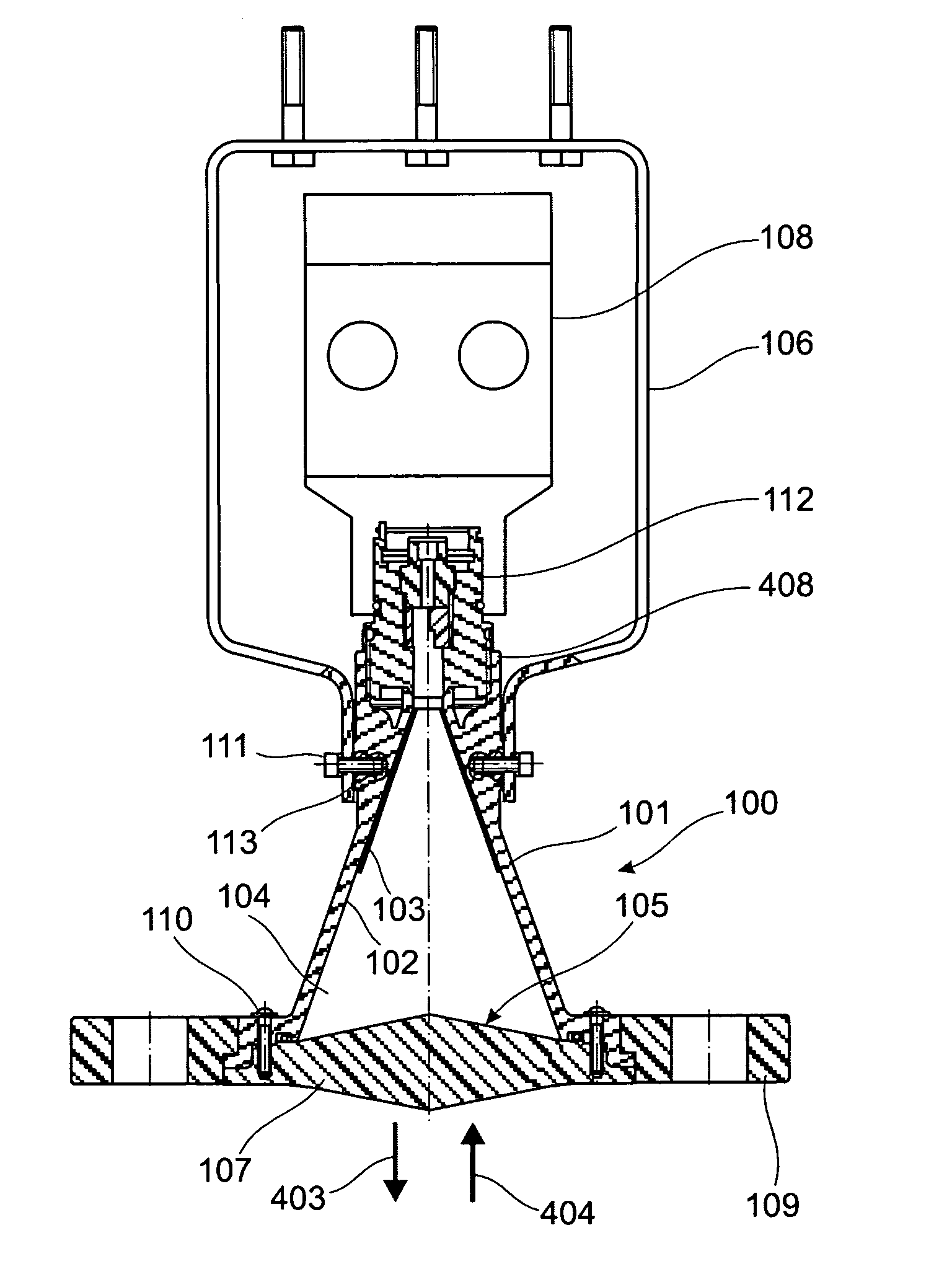
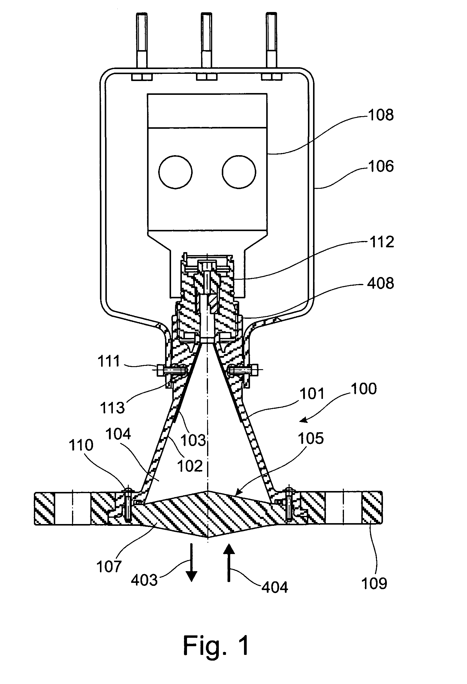
[0047]FIG. 1 is a diagrammatic cross-sectional view of a fill level radar according to one exemplary embodiment of the present invention. As shown in FIG. 1, the fill level radar essentially comprises a metallised plastic antenna 100 and a housing 108 whose interior accommodates an electronics module. Furthermore, a holding shackle 106 is provided.

[0048]In this arrangement the plastic antenna 100 is used for transmitting and receiving electromagnetic waves 403, 404. In this arrangement the waves 403 to be transmitted are generated within the electronics and are then fed into the antenna 100 by way of an adapter or connection piece 112 that comprises a waveguide. Conversely, incoming waves 404 are detected by the antenna 100 and are transmitted by way of the connection piece 112 with wavegu...


PUM


Abstract

A metalized plastic antenna includes a plastic antenna body with metallization on the inside. In this arrangement metallization is used for conducting electromagnetic waves. Furthermore, metallization may be implemented as a protective coating so that chemical resistance of the plastic antenna may be ensured even in the case of corrosive environmental conditions.

Description

RELATED APPLICATIONS[0001]This application claims the benefit of the filing date of the U.S.-Provisional Application Ser. No. 60 / 740,228 filed on Nov. 28, 2005 and of the German Patent Application Serial No. 10 2005 056 042.3 filed on Nov. 24, 2005, the disclosure of which both is hereby incorporated by reference.FIELD OF THE INVENTION[0002]The present invention relates to fill level measuring. In particular, the present invention relates to a metallised plastic antenna for a fill level radar, a fill level radar to determine the fill level in a tank, the use of such a metallised plastic antenna for fill level measuring, as well as to a method for producing such a metallised plastic antenna.TECHNOLOGICAL BACKGROUND[0003]Known fill level measuring devices comprise parabolic antennas or horn antennas that transmit or receive radar waves or microwaves in order to determine the fill level of a medium in a fill level container. The antenna of such a fill level measuring device is for exam...

Claims


Application Information

Patent Timeline
Patent Type & Authority Patents(United States)
IPC IPC(8): H01Q13/00
CPCG01F23/284H01Q1/225H01Q13/02H01Q13/0208H01Q19/062
Inventor MOTZER, JUERGENFEHRENBACH, JOSEFKIENZLE, KLAUSSUM, CHRISTIAN
Owner VEGA GRIESHABER GMBH & CO
Why Eureka
Eureka Blog
Learn More