
Tilt actuation for a rotorcraft

a rotorcraft and tilting technology, applied in the field of rotorcraft, can solve the problems of inability to accommodate very large moments that might be generated, the prior art actuator mechanism cannot practically produce such large forces, and the first motor will not stop the mechanism from functioning

Active Publication Date: 2011-01-18
KAREM AIRCRAFT INC
View PDF18 Cites 66 Cited by
  • Summary
  • Abstract
  • Description
  • Claims
  • Application Information

AI Technical Summary

Benefits of technology

"The present invention provides a way to control the tilt angle of an aircraft's nacelle using hingeless rotors on tilting nacelles. This can be done using an actuator or a mast moment generated by the rotors. By controlling the tilt angle of the nacelle, the orientation and flight mode of the aircraft can be manipulated. The use of mast moment to control the tilt angle reduces the loads that the actuator needs to produce and allows for continued control even if the actuator fails. The tilting mast can be locked in place using a brake to accommodate an actuator failure. The invention can be used in aircraft with two or more rotors on tilting nacelles, including those with first and second rotors in a tandem or side by side configuration."

Problems solved by technology

In this arrangement, a failure of the first motor will not stop the mechanism from functioning.
Since the prior art tilting mechanisms are all simple nacelle rotating devices, mechanized by linear actuators they are unable to accommodate very large moments that might be generated.
The prior art actuator mechanisms cannot practically produce such large forces.
Moreover, such these large forces place undesirably large demands on the actuator, especially when actuator failures must be accommodated for vehicle fault tolerance.

Method used


Image

  • Tilt actuation for a rotorcraft
  • Tilt actuation for a rotorcraft
  • Tilt actuation for a rotorcraft

Examples


Embodiment Construction

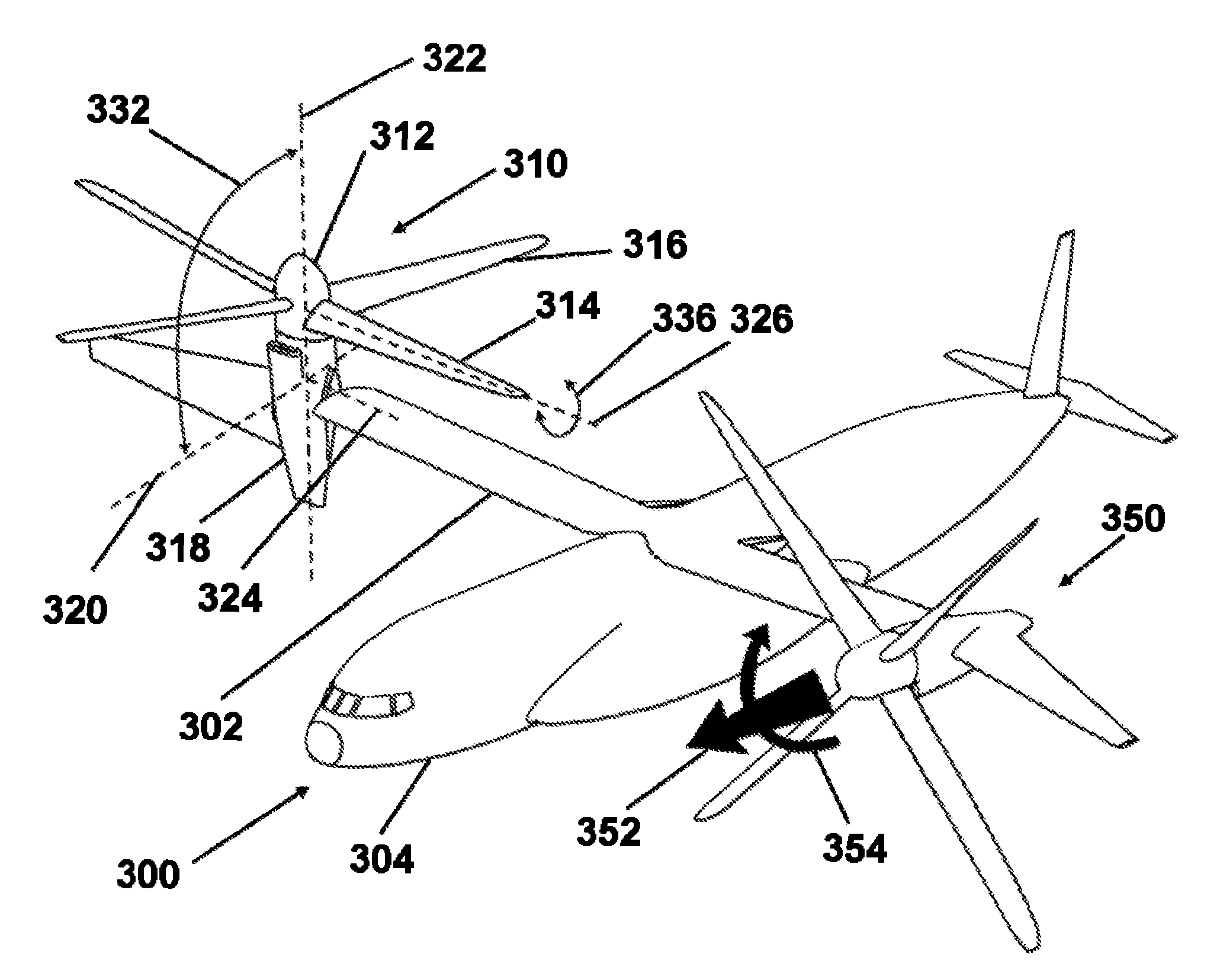
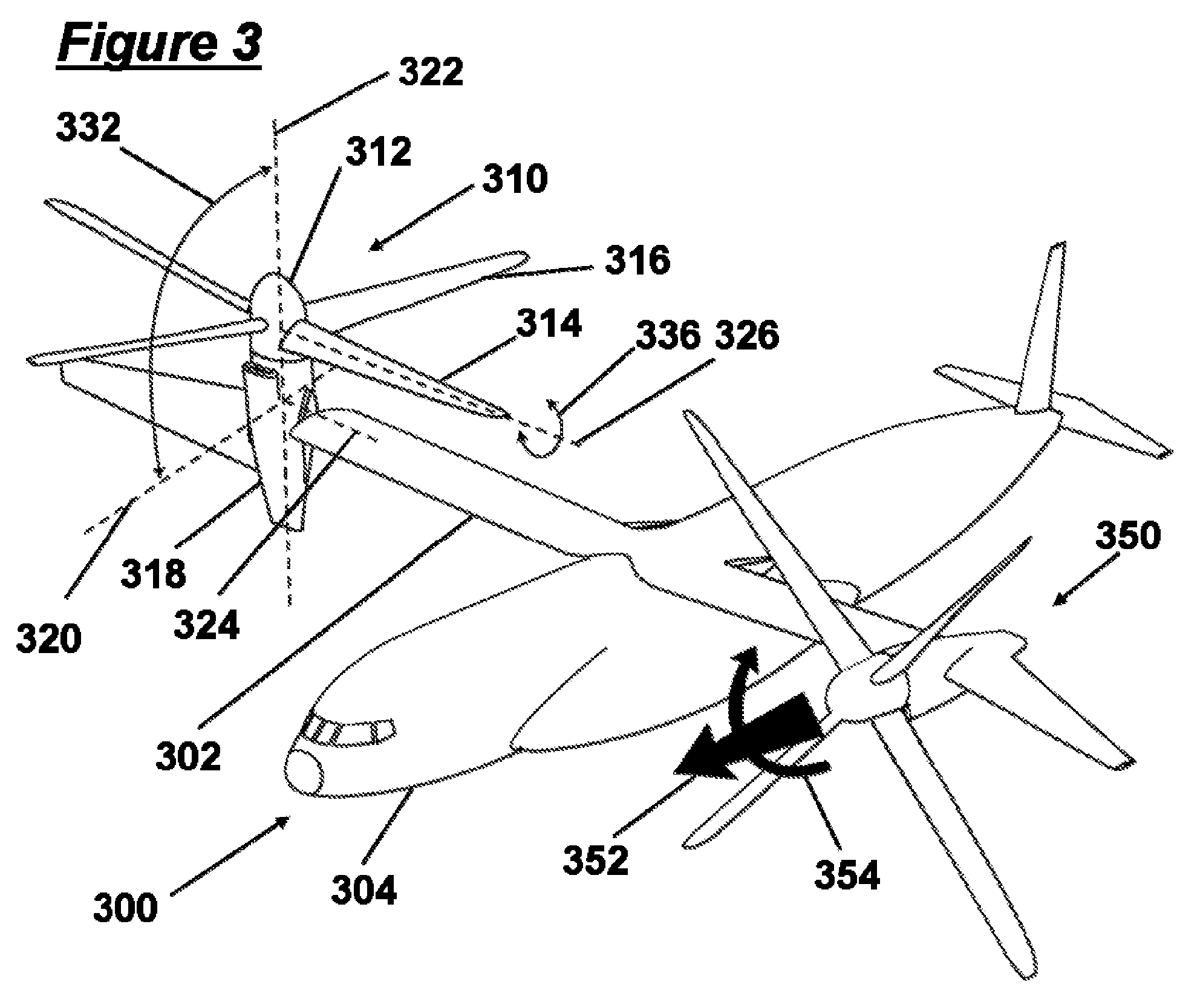
[0025]FIG. 3 is a perspective illustration of a preferred tiltrotor aircraft 300 comprising a wing 302 and fuselage 304, a first tilting rotor system 310 shown in helicopter-mode position, and a second tiling rotor system 350 shown in airplane cruise-mode. The wing 302 remains essentially fixed to the fuselage 304 during flight in either vertical takeoff mode or cruise flight. In preferred embodiments, the first and second rotors in the first and second rotor systems 310,350 are of a stiff hingeless variety such as that described in U.S. Pat. No. 6,641,365 to Karem. Such rotor systems 350 transmit considerable forces and moments to the wing 302 and fuselage 304. In either helicopter-mode flight or airplane-mode cruise flight, the rotor generates thrust as indicated by block arrow 352 and moment as indicated by block arrow 354. Hingeless rotor systems for tiltrotors are unlike prior art gimbaled systems in that they can transmit considerable large moments, also referred to as mast mo...


PUM


Abstract

An aircraft is equipped with hingeless rotors on tilting nacelles, and the tilt angles of the nacelles are controlled using either or both of an actuator and a mast moment generated by a hingeless rotor. An aircraft with two or more rotors on tilting nacelles can achieve control of yaw orientation by differential tilt of its nacelles or masts. Hingeless rotors can be manipulated to control a tilt angle of a mast by changing the rotor blade pitch to produce a mast moment. The rotor and nacelle tilt of a tiltrotor rotorcraft can be controlled and effected in order to manipulate the yaw orientation and flight mode of a rotorcraft such as a tiltrotor. The use of mast moment to control nacelle tilt angle can reduce tilt actuator loads and allows for the control of nacelle tilt even in the event of an actuator failure.

Description

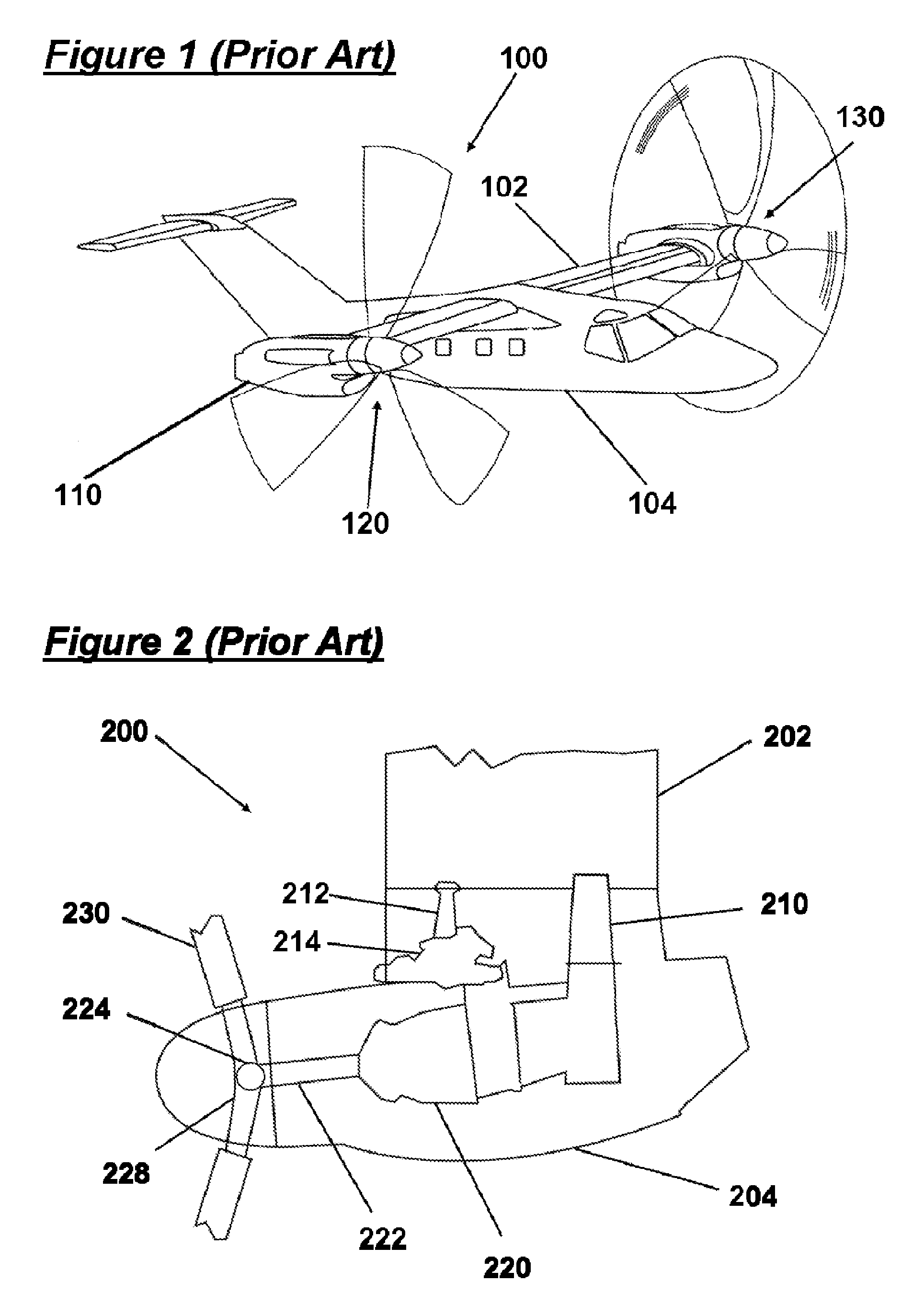
[0001]This application claims priority to U.S. Provisional Application Ser. No. 61 / 044,429 filed Apr. 11, 2008 which is incorporated by reference herein in its entirety.FIELD OF THE INVENTION[0002]The field of the invention is rotorcraft.BACKGROUND[0003]Tilt rotor and tilt wing aircraft convert between a forward flight cruise mode and a hover mode by converting the orientation of their propellers or rotors and nacelles. FIG. 1 shows a typical prior art tiltrotor aircraft 100 comprising a wing 102 and fuselage 104 with a first rotor 120 and first nacelle 114 in aircraft cruise mode corresponding with a generally horizontal position of the nacelle 104. The aircraft is also equipped with a second rotor 130 on the opposite end of the wing 102. In a typical tilt rotor aircraft 100, the nacelle 104 is also capable of operation in a generally vertical position used in helicopter mode flight. The nacelle 104 tilt angle is usually effected using a tilt actuator and mechanism to convert from ...

Claims


Application Information

Patent Timeline
Patent Type & Authority Patents(United States)
IPC IPC(8): B64C27/22
CPCB64C27/08B64C27/52B64C29/0033
Inventor KAREM, ABEWAIDE, WILLIAM MARTINPATT, DAN
Owner KAREM AIRCRAFT INC
Learn More