Liquid crystal display having image edge enhancement circuit and image edge enhancement method for same

a liquid crystal display and enhancement circuit technology, applied in image enhancement, instruments, television systems, etc., can solve problems such as blue edges of displaying images

Active Publication Date: 2011-01-11
INNOLUX CORP
View PDF16 Cites 0 Cited by
  • Summary
  • Abstract
  • Description
  • Claims
  • Application Information

AI Technical Summary

Problems solved by technology

However, some adjacent image signal showing an edge of an image may have a large color difference therebetween, and a distortion after the image signal YCbCr be transferred into a RGB signal, and a blur may occur in the edge of the displaying image.

Method used


Image

  • Liquid crystal display having image edge enhancement circuit and image edge enhancement method for same
  • Liquid crystal display having image edge enhancement circuit and image edge enhancement method for same
  • Liquid crystal display having image edge enhancement circuit and image edge enhancement method for same

Examples


Embodiment Construction

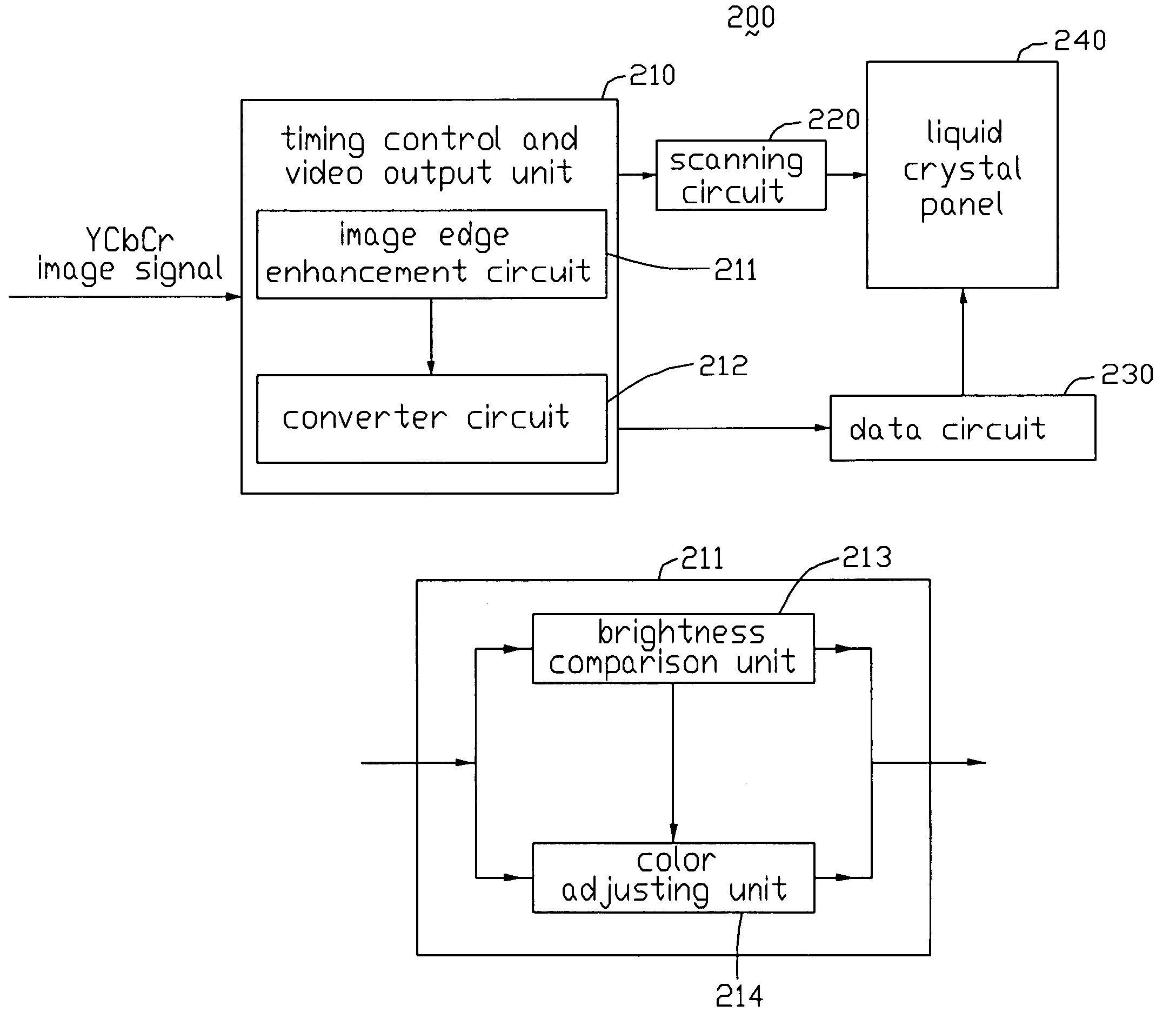
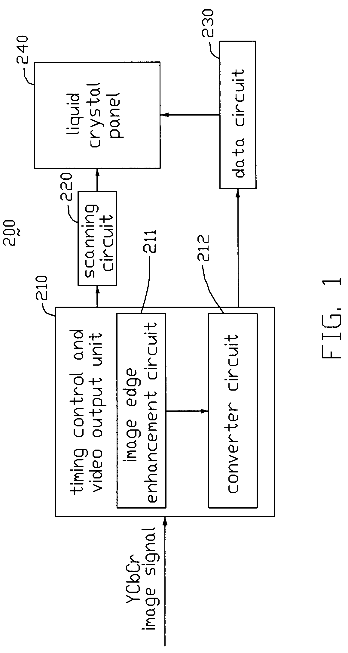
[0022]Referring to FIG. 1, this is a block diagram of a liquid crystal display 200 in accordance with the preferred embodiment of the present invention, showing an image displaying process thereof. The liquid crystal display 200 includes a timing control and video output unit 210, a scanning circuit 220, a data circuit 230, and a liquid crystal panel 240 having a plurality of pixels (not shown) defined thereon. The timing control and video output unit 110 includes an image edge enhancement circuit 211 and a converter circuit 212.

[0023]Image signals YCbCr are used in the liquid crystal display 200. In general, the image signals YCbCr are compressed, in order to reduce the volume thereof during transmission. The compressed image signals YCbCr are transmitted to the timing control and video output unit 210. Each image signal YCbCr is composed of three factors, a brightness factor Y, and two color factors Cb, Cr. The image signal YCbCr is transformed into a corresponding RGB (red, green...


PUM


Abstract

An exemplary liquid crystal display (200) includes a data circuit (230), a timing control and video output unit (210). The timing control and video output unit includes an image edge enhancement circuit (211) configured for sharpening at least one edge of an image shown by the liquid crystal display, and a converter (212). The image edge enhancement circuit includes a color adjusting unit (214) and a brightness comparison unit (213). The color adjusting unit configured for receiving and adjusting Cb, Cr color factors of the YCbCr image signals according to a result of comparison of brightness factors Y of the YCbCr image signals received from the brightness comparison unit. The adjusted YCbCr image signal is converted to a corresponding RGB signals by the converter circuit and the RGB signals are sent to the data driving circuit.

Description

FIELD OF THE INVENTION[0001]The present invention relates to a liquid crystal display having an image edge enhancement circuit, which is configured to sharpen images shown by the liquid crystal display.GENERAL BACKGROUND[0002]A typical liquid crystal display generally includes a display panel and a backlight module for illuminating the display panel. The display panel includes two glass substrates, and a liquid crystal layer is sealed between the substrates. The display panel receives image signals from a data circuit, and displays desired images according to the image signals.[0003]Referring to FIG. 5, this is a block diagram of a conventional liquid crystal display 100, showing an image displaying process thereof. The liquid crystal display 100 includes a timing control and video output unit 110, a scanning circuit 120, a data circuit 130, and a liquid crystal panel 140 having a plurality of pixels (not shown) defined thereon. The timing control and video output unit 110 includes ...

Claims


Application Information

Patent Timeline
Patent Type & Authority Patents(United States)
IPC IPC(8): G09G3/36
CPCG09G3/3611G06T5/003G09G2340/02G06T2207/10024G06T2207/20192
Inventor CHAN, KAI-CHIEH
Owner INNOLUX CORP
Why Eureka
Try Eureka