
Nanocrystal powered nanomotor

a nano-motor and nano-crystal technology, applied in the field of carbon nanotubes, can solve the problems of limiting the application potential of many proven macroscopic motor designs to nanometer length scales, affecting the performance of many motors, and achieving the effect of expanding flexibility

Active Publication Date: 2011-01-04
RGT UNIV OF CALIFORNIA
View PDF22 Cites 5 Cited by
  • Summary
  • Abstract
  • Description
  • Claims
  • Application Information

AI Technical Summary

Benefits of technology

[0020]Laser cooling applications demand single-frequency operation in the visible (red) and IR wavelength region. Sodium, rubidium and cesium are the most common atoms used in cooling experiments, and Coherent's 899-21 Actively Stabilized, Single-Frequency Ring Laser (or MBR-110 Monolithic Block Resonator) is well suited to the study of these atoms. The single reference cavity of the Coherent 899-21 provides frequency stabilization for operation at linewidths of less than 500 kHz, and the system is available in either a Ti:Sapphire configuration (700 to 1000 nm tuning range) or a dye configuration (visible to over a micron tuning range) for extensive flexibility in the study of new atoms and optical trap experiments. The 899-21 ring laser is the only commercially available continuous wave (cw) system with a narrow linewidth single-frequency active stabilization feature.

Problems solved by technology

The direct scaling of many proven macroscopic motor designs to nanometer length scales appears challenging.
However, such structurally complex biomotors have limited force capability and require tightly controlled chemical environments for operation (Ref 9), features which restrict their applications potential and make them questionable models for synthetic analogues.

Method used


Image

  • Nanocrystal powered nanomotor
  • Nanocrystal powered nanomotor
  • Nanocrystal powered nanomotor

Examples


Embodiment Construction

I. Generalized Method and Apparatus

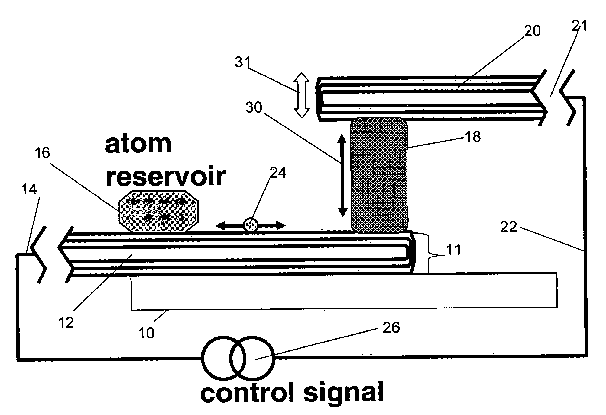
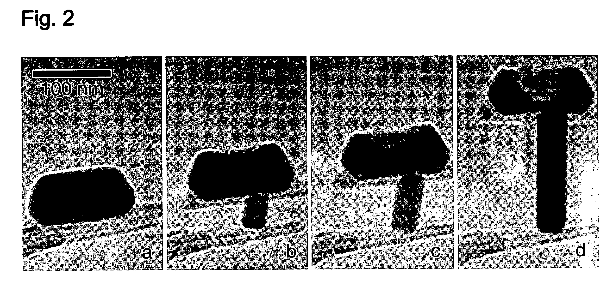
[0032]The present nanocrystal powered nanomotor provides a nanoscale linear motor, powered by a single metal nanocrystal ram sandwiched between mechanical lever arms. Low-level electrical voltages applied to the lever arms grow or shrink the nanocrystal, virtually atom-by-atom, in a controlled manner. The length of the ram is adjustable from zero to more than 150 nm, with extension speeds exceeding 1900 nm / s. This synthetic linear motor may find application in inorganic nanoelectromechanical systems (NEMS) devices as well as in hybrid synthetic / bio-motors and related structures.

[0033]Described below is the successful construction and operation of a synthetic and apparently wear-free cyclical nanoscale linear motor, powered by a single solid-state metal nanocrystal ram. The ram length and extension / retraction rates are precisely controlled via low-level dc voltage signals applied to mechanical lever arms contacting the ram. The entire motor may be c...


PUM


Abstract

A nanoscale nanocrystal which may be used as a reciprocating motor is provided, comprising a substrate having an energy differential across it, e.g. an electrical connection to a voltage source at a proximal end; an atom reservoir on the substrate distal to the electrical connection; a nanoparticle ram on the substrate distal to the atom reservoir; a nanolever contacting the nanoparticle ram and having an electrical connection to a voltage source, whereby a voltage applied between the electrical connections on the substrate and the nanolever causes movement of atoms between the reservoir and the ram. Movement of the ram causes movement of the nanolever relative to the substrate. The substrate and nanolever preferably comprise multiwalled carbon nanotubes (MWNTs) and the atom reservoir and nanoparticle ram are preferably metal (e.g. indium) deposited as small particles on the MWNTs. The substrate may comprise a silicon chip that has been fabricated to provide the necessary electrodes and other electromechanical structures, and further supports an atomic track, which may comprise an MWNT.

Description

CROSS-REFERENCE TO RELATED APPLICATIONS[0001]This Patent Application is a CIP and claims benefit to patent application Ser. No. 11 / 085,397, filed Mar. 21, 2005, now U.S. Pat. No. 7,341,651 entitled “Nanoscale Mass Conveyors,” and claims benefit to Provisional Patent Application Ser. 60 / 615,782, filed Oct. 4, 2004, entitled “Nanocrystal Powered Nanomotor”, both of which are hereby incorporated by reference.STATEMENT OF GOVERNMENTAL SUPPORT[0002]This invention was made during work supported by U.S. Department of Energy under Contract No. DE-AC02-05CH11231 and by the National Science Foundation under Grant No. CCR 0210176. The government has certain rights in this invention.REFERENCE TO SEQUENCE LISTING OR COMPACT DISK[0003]NONEBACKGROUND OF THE INVENTION[0004]1. Field of the Invention[0005]The present invention relates to the field of carbon nanotubes and to the field of molecular sized electromechanical devices which contain nanoscale levers, such as carbon nanotubes and the like.[00...

Claims


Application Information

Patent Timeline
Patent Type & Authority Patents(United States)
IPC IPC(8): H02N11/00H02N1/04
CPCB81B3/0021B81B2201/038B82Y15/00Y10T117/1004Y10S977/752Y10S977/733Y10S977/725B82Y30/00
Inventor REGAN, BRIAN C.ZETTL, ALEXANDER K.ALONI, SHAUL
Owner RGT UNIV OF CALIFORNIA
Learn More